Altera Arria 10 Avalon-MM DMA User Manual
Page 65
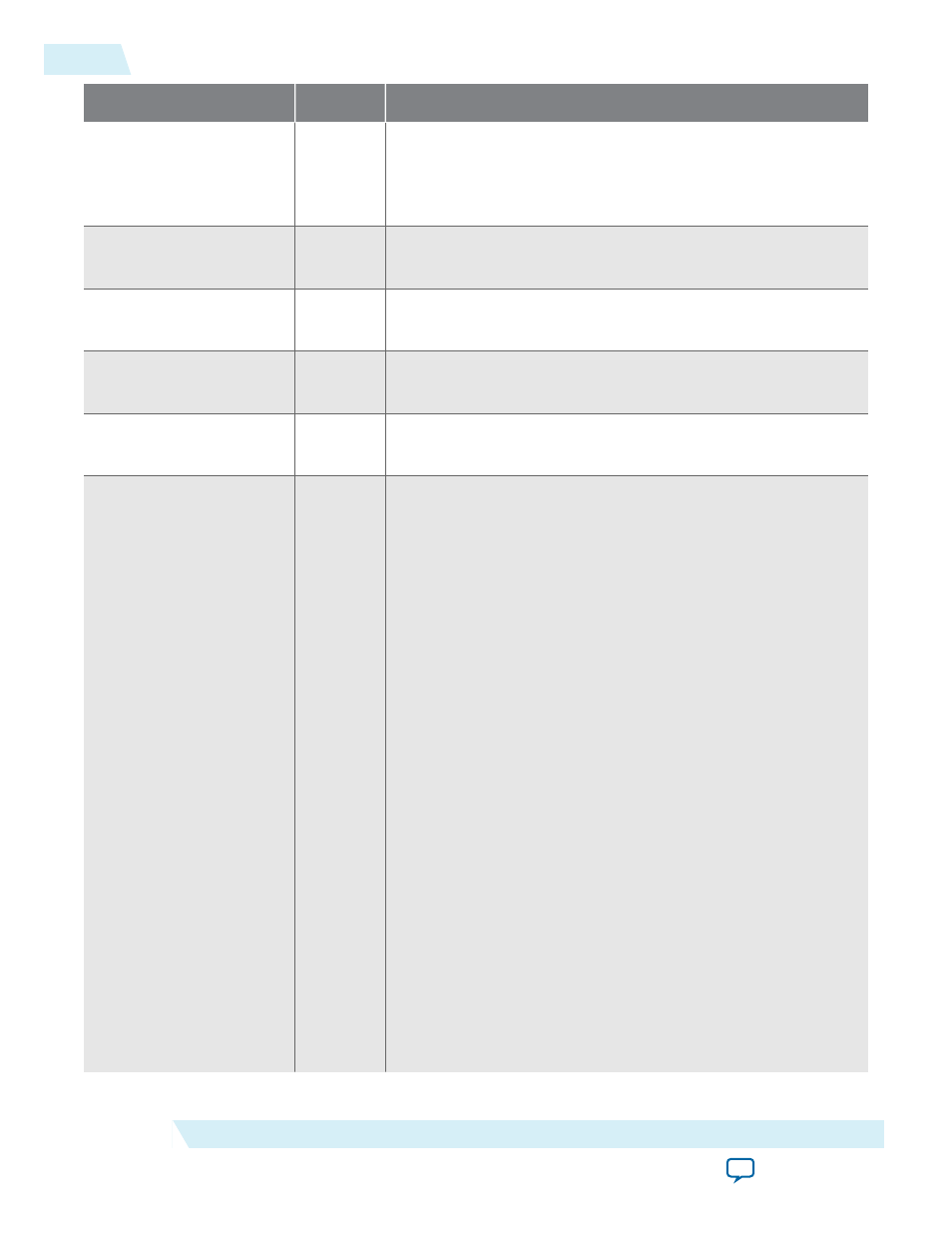
Signal
Direction
Description
rxdatak0[3:0]
Input
Data/Control bits for the symbols of receive data. Bit 0
corresponds to the lowest-order byte of
rxdata
, and so on. A
value of 0 indicates a data byte. A value of 1 indicates a control
byte. For Gen1 and Gen2 only.
rxelecidle0
Input
Receive electrical idle <n>. When asserted, indicates detection of
an electrical idle.
rxpolarity0
Output
Receive polarity <n>. This signal instructs the PHY layer to
invert the polarity of the 8B/10B receiver decoding block.
rxstatus0[2:0]
Input
Receive status <n>. This signal encodes receive status and error
codes for the receive data stream and receiver detection.
rxvalid0
Input
Receive valid <n>. This symbol indicates symbol lock and valid
data on
rxdata
<n> and
rxdatak
<n>.
sim_pipe_
ltssmstate0[4:0]
Input and
Output
LTSSM state: The LTSSM state machine encoding defines the
following states:
• 5’b00000: Detect.Quiet
• 5’b 00001: Detect.Active
• 5’b00010: Polling.Active
• 5’b 00011: Polling.Compliance
• 5’b 00100: Polling.Configuration
• 5’b00101: Polling.Speed
• 5’b00110: config.LinkwidthsStart
• 5’b 00111: Config.Linkaccept
• 5’b 01000: Config.Lanenumaccept
• 5’b01001: Config.Lanenumwait
• 5’b01010: Config.Complete
• 5’b 01011: Config.Idle
• 5’b01100: Recovery.Rcvlock
• 5’b01101: Recovery.Rcvconfig
• 5’b01110: Recovery.Idle
• 5’b 01111: L0
• 5’b10000: Disable
• 5’b10001: Loopback.Entry
• 5’b10010: Loopback.Active
• 5’b10011: Loopback.Exit
• 5’b10100: Hot.Reset
• 5’b10101: L0s
• 5’b11001: L2.transmit.Wake
5-24
PIPE Interface Signals
UG-01145_avmm_dma
2015.05.14
Altera Corporation
IP Core Interfaces