Altera Arria 10 Avalon-MM DMA User Manual
Page 85
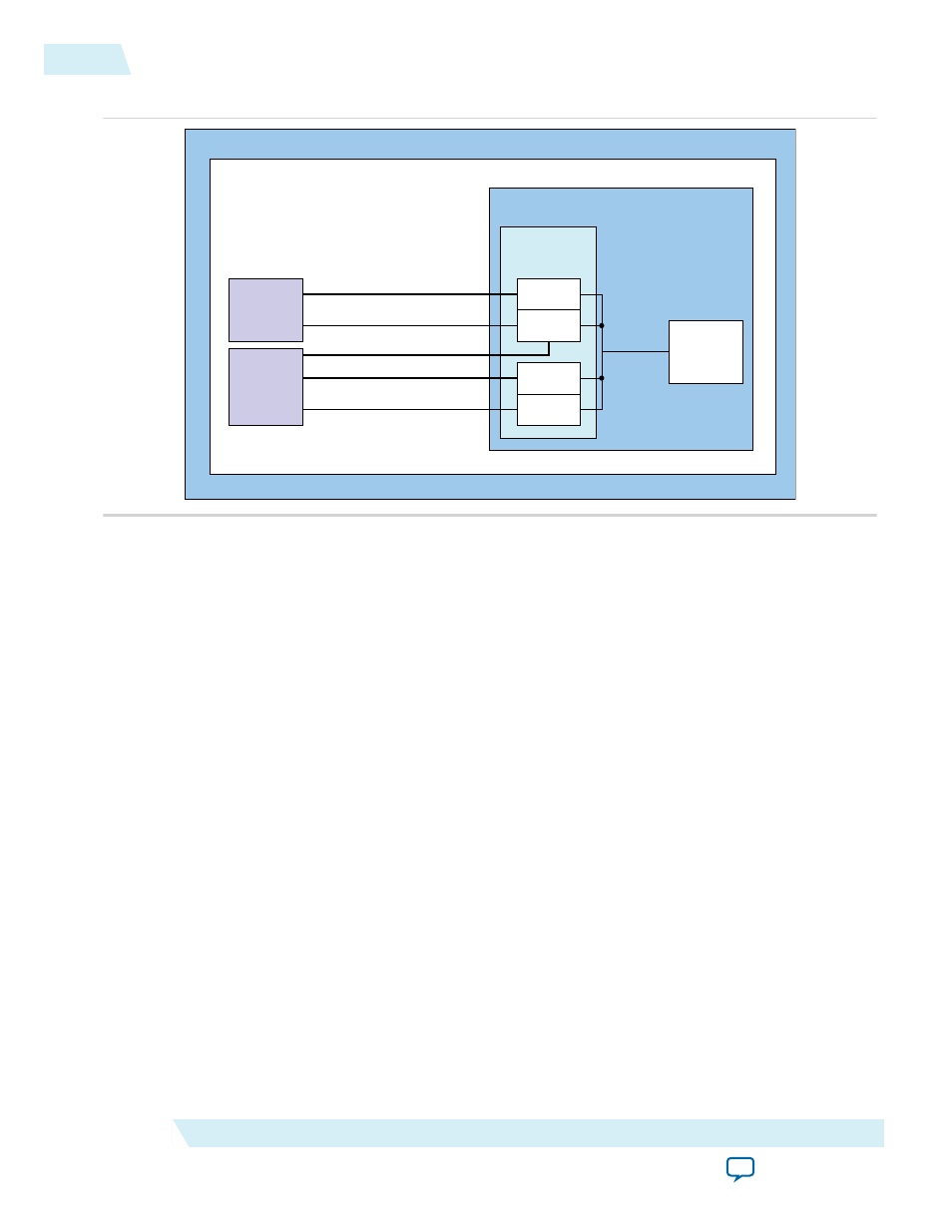
Figure 6-9: Block Diagram for External Descriptor Controller
Altera FPGA
Memory
Read DMA
Write DMA
Hard IP
for PCIe
RX Master
TX Slave
DMA
Descriptor
Controller
Avalon-MM Burst Master 256 Bits
Avalon-MM Master 256 Bits
Avalon-MM Master Single DWORD
Avalon-MM Slave Single DWORD
Avalon-ST Control/Status
Avalon-ST
256 Bits
PCIe Avalon-MM
Bridge
Hard IP for PCIe Using Avalon-MM Interface
with External Descriptor Controller
Qsys System
The Read DMA transfers data from the PCIe address space to Avalon-MM address space. It issues
memory read TLPs on the PCIe link. It writes the data returned to a memory in the Avalon-MM address
space. The source address is the address for the data in the PCIe address space. The destination address is
in the Avalon-MM address space.
The Write DMA reads data from the Avalon-MM address space and writes to the PCIe address space. It
issues memory write TLPs on the PCIe link. The source address is in the Avalon-MM address space. The
destination address is in the PCIe address space.
The DMA Descriptor Controller records the completion status for read and write descriptors in separate
status tables. Each table has 128 dword entries that correspond to the 128 descriptors. The Descriptor
Controller writes a 1 to the
done
bit of the status dword to indicate successful completion. The Descriptor
Controller also sends an MSI interrupt for the final descriptor. After receiving this MSI, host software can
poll the
done
bit to determine status. The status table precedes the descriptor table in memory. The
Descriptor Controller does not write the
done
bit nor send an MSI as each descriptor completes. It only
writes the
done
bit or sends an MSI for the descriptor whose ID is stored in the
RD_DMA_LAST PTR
or
WR_DMA_LAST_PTR
registers. The Descriptor Controller supports out-of-order completions. Consequently,
it is possible for the
done
bit to be set before all descriptors have completed.
The status entries for the 128 descriptors are stored in the 128 consecutive dwords specified by the values
programmed into the
RC Read Descriptor Base
and
RC Write Descriptor Base
registers. The actual
descriptors are stored immediately after the status entries at offset 0x200 from the values programmed
into the
RC Read Descriptor Base
and
RC Write Descriptor Base
registers. The status and
descriptor table must be located on a 32-byte boundary in Root Complex memory.
Note: For example, if 128 descriptors are specified and all of them execute, then 127 is written to the
RD_DMA_LAST_PTR
or
WR_DMA_LAST_PTR
register to start the DMA. The DMA Descriptor
Controller only writes the
done
bit when descriptor 127 completes. To get intermediate status
updates, host software should write multiple IDs into the last pointer register. For example, to get
an intermediate status update when half of the 128 read descriptors have completed, host software
should complete the following sequence:
6-16
DMA Descriptor Controller Registers
UG-01145_avmm_dma
2015.05.14
Altera Corporation
Registers