Watson-Marlow MM420 User Manual
Page 107
Issue 10/06
3 Functions
MICROMASTER 420 Operating Instructions
6SE6400-5AA00-0BP0
107
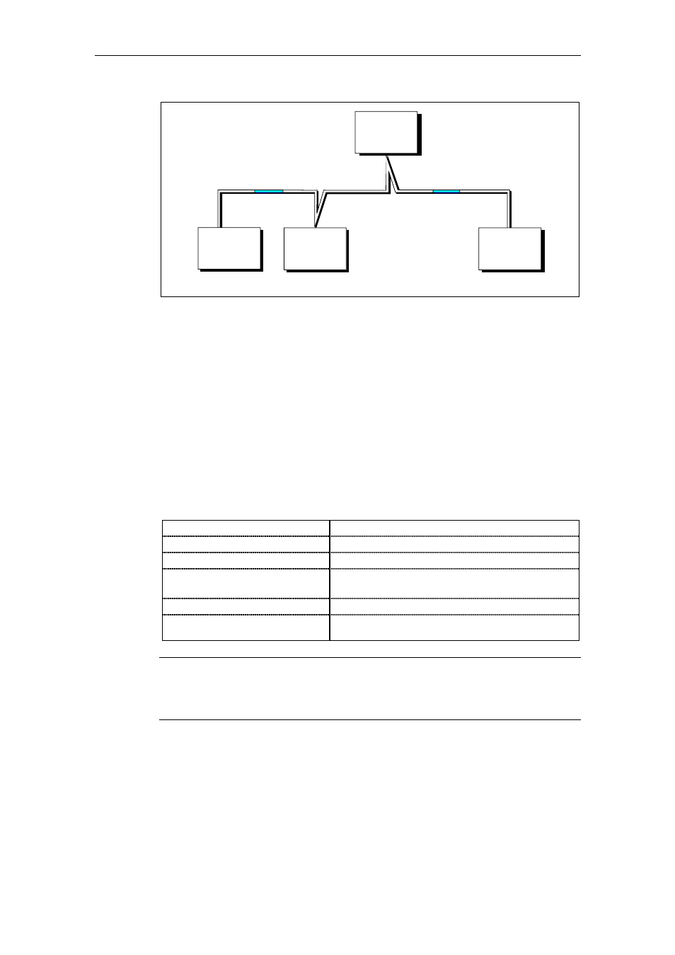
Master
Slave
Maximum 32 slaves
First node
Last node
Slave
Slave
Fig. 3-37
USS bus topology
The two ends of a bus line (first node and last node) must be terminated with bus
terminating networks. (refer to Section 3.7.1.3). Point-to-point connections are
handled just like bus connections. One node has the master function and the other
has the slave function.
Data is transferred in accordance with Standard EIA 485. RS 232 can be used for
point-to-point links. Data transfer is always half-duplex
− i.e. alternating between
transmitting and receiving
− and it must be controlled by the software. The half-
duplex technique allows the same cables to be used for both data-transfer
directions. This permits simple and inexpensive bus cabling, operation in
environments subject to interference and a high data transfer rate.
A shielded, twisted two-wire cable is used as the bus cable.
Table 3-15
Structural data
Conductor diameter
2 x
≈ 0,5 mm
2
Conductor
≥ 16 x ≤ 0,2 mm
Lay ratio
≥ 20 twists / m
Overall shield
Braided, tin-plated copper wire, diameter
∅
≥
1,1 mm
2
85 % optical coverage
Overall diameter -
∅
5 mm
External sheath
Depending on the requirements regarding flame retardation,
deposits after burning etc.
NOTE
All information should only be considered as a recommendation.
Deviations or different measures may be required depending on the particular
requirements, the specific application and the conditions on site.