3 uss bus configuration via com link (rs485) – Watson-Marlow MM420 User Manual
Page 118
3 Functions
Issue 10/06
MICROMASTER 420 Operating Instructions
118
6SE6400-5AA00-0BP0
3.7.1.3
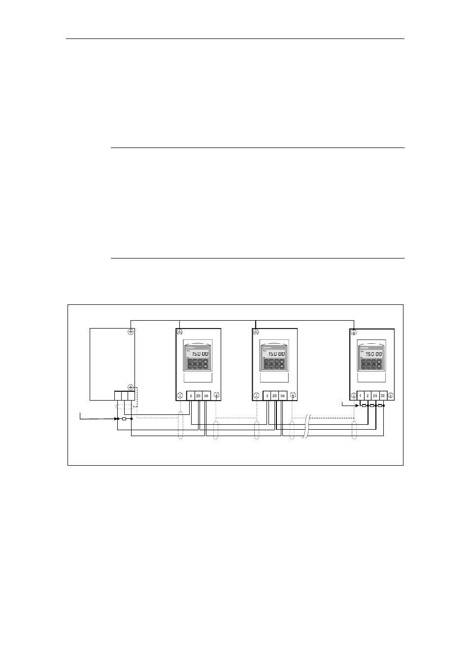
USS bus configuration via COM link (RS485)
In order to ensure disturbance-free USS operation, the bus cable must be
terminated at both ends using bus terminating resistors. In this case, the bus cable
from the first node up to the last node should be considered as one bus cable – so
that the USS bus should be terminated twice. For the first bus node [device] (e.g.
master) and last bus node [device] (e.g. drive converter), th bus terminating
resistor must be switched-in.
NOTE
♦ When supplied, the bus terminating resistors are not switched-in!
♦ Please note that you only switch-in the bus terminating at the first bus node
[device] and last bus note! The bus terminating resistors should be always set
when the system is powered-down!
♦ Data transfer errors on the bus are possible!
In active bus operation, nodes where the terminating resistor is switched-in,
must always be powered-up. The terminating resistor draws the voltage from
the connected device. This is the reason that the terminating resistor is no
longer effective when the node is powered down .
The following diagram shows the structure of a bus connection through terminals
14, 15:
Screening
Screening
Screening
Potential equilization cable
RS485 terminator
RS48
5 ter
m
inat
or
Master
0 V
(M)
• a terminating resistor must be connected at the first and last node on the bus cable
• no bus termination for other nodes
Fig. 3-40
Connecting the USS bus cable