12 setpoint channel – Watson-Marlow MM420 User Manual
Page 132
3 Functions
Issue 10/06
MICROMASTER 420 Operating Instructions
132
6SE6400-5AA00-0BP0
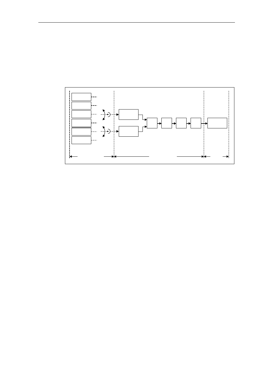
3.12 Setpoint
channel
The setpoint channel (refer to Fig. 3-49) forms the coupling element between the
setpoint source and the motor control. MICROMASTER has a special characteristic
which allows the setpoint to be entered simultaneously from two setpoint sources.
The generation and subsequent modification (influencing the direction, suppression
frequency, up/down ramp) of the complete setpoint is carried-out in the setpoint
channel.
MOP
ADC
FF
USS
BOP link
USS
COM link
CB
COM link
Setpoint source
Main
setpoint
Additonal
setpoint
SUM
AFM
Limit
RFG
Setpoint channel
Motor
control
Motor
control
Fig. 3-49
Setpoint channel
3.12.1
Summation and modification of the frequency setpoint (AFM)
Parameter range:
P1070 – r1114
Warnings -
Fault -
Function chart number:
FP5000, FP5200
For applications where the control quantities are generated from central control
systems, fine tuning is often required locally on-site (correction quantity). For
MICROMASTER, this can be very elegantly realized using the summation point
where the main and supplementary (additional) setpoint are added in the setpoint
channel. In this case, both quantities are simultaneously read-in via two separate
or one setpoint source and summed in the setpoint channel. Depending on
external circumstances, the supplementary setpoint can be dynamically
disconnected or switched-in to the summation point (refer to Fig. 3-50). This
functionality can be used to advantage, especially for discontinuous processes.