3 reference quantities – Watson-Marlow MM420 User Manual
Page 50
3 Functions
Issue 10/06
MICROMASTER 420 Operating Instructions
50
6SE6400-5AA00-0BP0
3.1.3 Reference
quantities
Parameter range:
P2000 - P2002
When being output or read-in by the drive inverter, physical quantities are
normalized or de-normalized. This conversion is made directly by the particular
interface using the reference quantities. The normalization / de-normalization is
carried-out for the following interfaces:
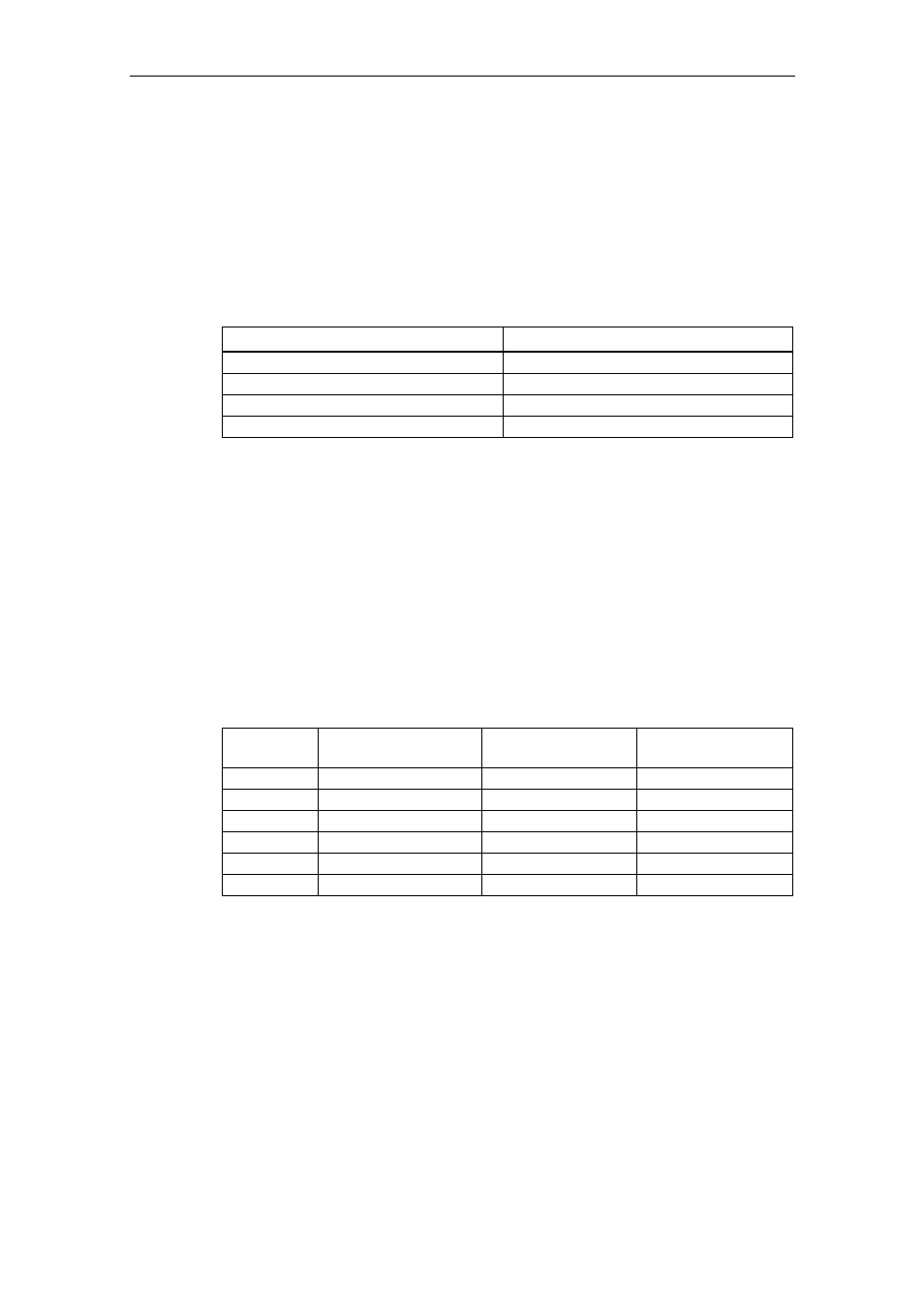
Table 3-5
Normalized interfaces
Interface 100
%
Analog input (voltage input)
10 V
Analog output (current output)
20 mA
USS 4000
h
CB 4000
h
Further, a normalization is carried-out for a BICO connection if the connector
output (CO) represents a physical quantity and the connector input (CI) a
normalized (percentage) quantity (e.g. PID controller). A de-normalization is
carried-out if the inverse applies.
Reference quantities (normalization quantities) are intended to allow setpoints and
actual signals to be represented in a uniform, standard way (normalization / de-
normalization of physical quantities such as setpoint and actual frequency). This
also applies to permanently set parameters that are assigned the "percentage"
units. A value of 100 % corresponds in this case to a process data value PZD of
4000 h (USS or CB) or a current value of 20 mA (analog output) or a voltage value
of 10 V (analog input). The following reference parameters and permanently saved
reference values are available:
Table 3-6
Normalization functions
Parameter
Designation
Value (100 % / 4000
h)
Units
P2000 Reference
frequency
P2000
Hz
P2001 Reference
voltage P2001
V
P2002 Reference
current P2002
A
- Reference
speed
P2000
* 60 / r0313
RPM
-
Reference temperature
100 °C
°C
-
Reference energy
100 kWh
kWh