11 pid controller (technological controller) – Watson-Marlow MM420 User Manual
Page 128
3 Functions
Issue 10/06
MICROMASTER 420 Operating Instructions
128
6SE6400-5AA00-0BP0
3.11
PID controller (technological controller)
Parameter range:
P2200
P2201 – r2294
Warnings -
Faults -
Function chart number:
FP3300, FP3310, FP3400, FP5100
Features:
- cycle time:
8 ms
MICROMASTER has an integrated technological controller (PID controller, enabled
via P2200). This can be used to process basic higher-level control functions. These
typically include:
Pressure control for extruders
Water level control for pump drives
Temperature control for fan drives
And similar control tasks
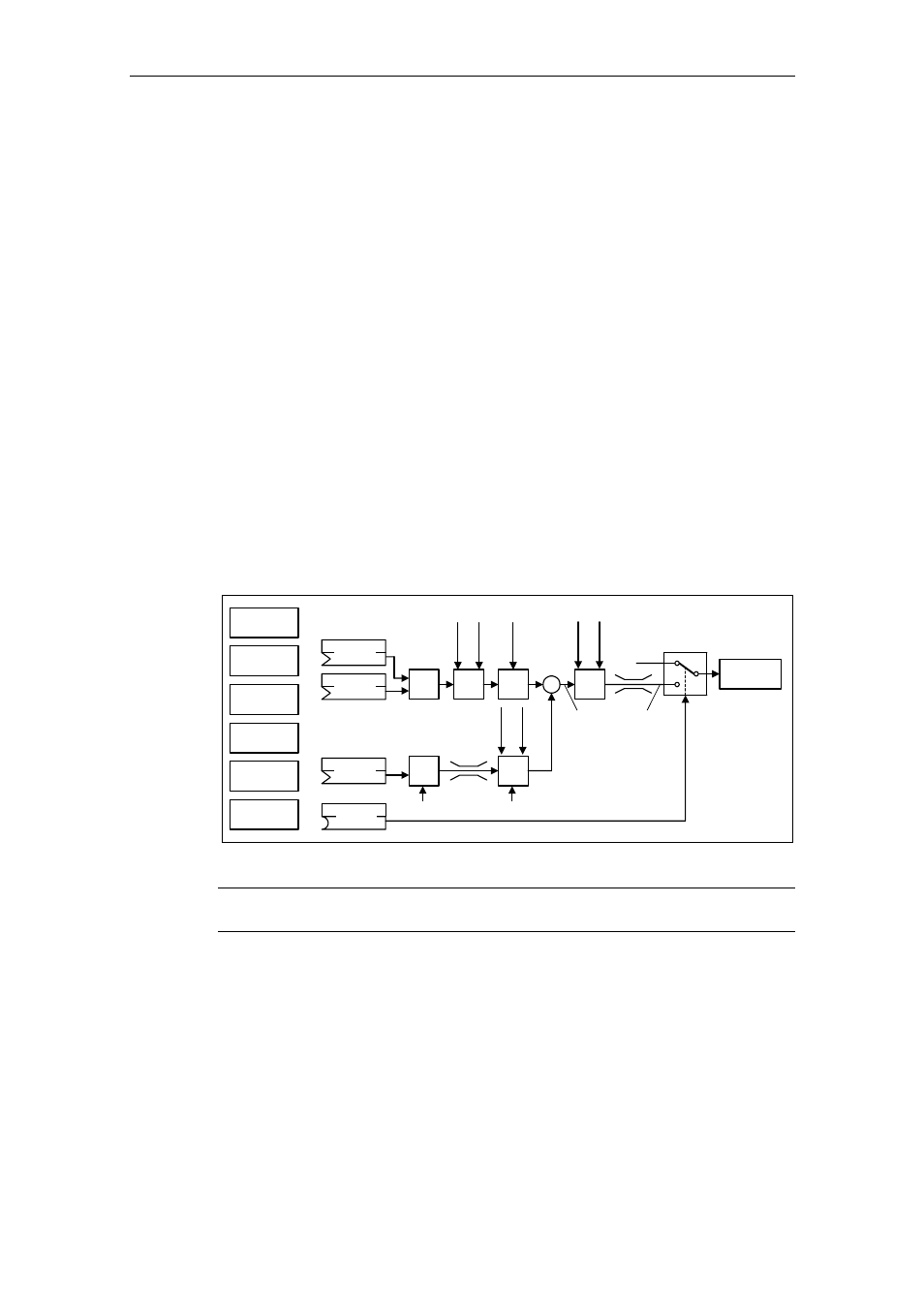
The technological setpoints and actual values can be entered via the PID
motorized potentiometer (PID-MOP), PID fixed setpoint (PID-FF), analog input
(ADC) or via serial interfaces (USS on BOP link, USS on COM link, CB on COM
link) (refer to the example). The appropriate parameterization of the BICO
parameter defines which setpoints or actual values are to be used (refer to Fig.
3-46).
PID
MOP
ADC
PID
SUM
PID
PID
FF
USS
BOP link
USS
COM link
CB
COM link
P2254
P2253
PID
RFG
PID
PT1
− ∆
PID
P2200
P2264
PID
PT1
PID
SCL
Output
PID
0
1
Motor
control
P225
7
P225
8
P226
1
P2271
P2
269
P2
270
P2265
P22
80
P22
85
Fig. 3-46
Structure of the technological controller (PID controller)
NOTICE
Changes in parameter P2200 take effect only after a fresh ON command.