Watson-Marlow MM420 User Manual
Page 146
3 Functions
Issue 10/06
MICROMASTER 420 Operating Instructions
146
6SE6400-5AA00-0BP0
If the frequency inverter directly controls the motor holding brake using the
relay integrated in the frequency inverter, then the max. load capability of
this relay should be carefully taken into consideration in conjunction with the
voltage/current data of the holding brake. The following applies for the relay
integrated in the frequency inverter:
−
30 V DC / 5 A
−
250 V AC / 2 A
If this value is exceeded, an additional relay should, for example, be used.
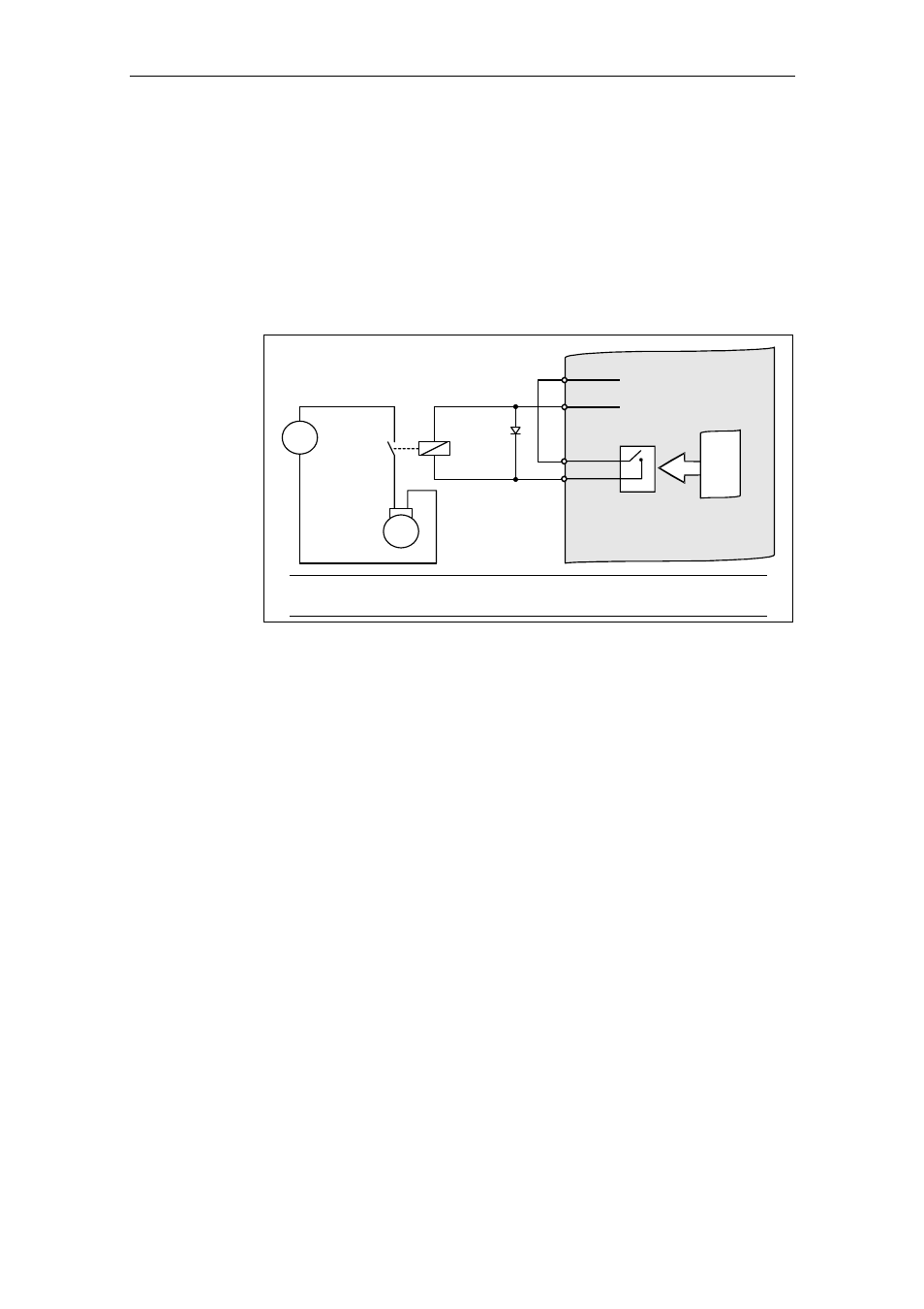
♦ Indirectly connecting relay output via an additional relay
8
9
Output 0 V, max. 100 mA
(isolated)
Output +24 V, max. 100 mA
(isolated)
24 V
0 V
Relay
M
3
~
=
COM
NO
10
11
CPU
MICROMASTER 420
Motor with
motor
holding brake
Free-
wheeling
diode
Caution
The relay may not overload the internal 24 V power supply!
Fig. 3-61
Indirect motor holding brake connection