Fast detection configuration example, Network requirements, Configuration procedure – H3C Technologies H3C S12500 Series Switches User Manual
Page 110
99
# Enable RRPP.
[DeviceF] rrpp enable
7.
Configure RRPP ring groups on Device B and Device C after the configurations:
# Create RRPP ring group 1 on Device B, and add subrings 2 and 3 to the RRPP ring group.
[DeviceB] rrpp ring-group 1
[DeviceB-rrpp-ring-group1] domain 2 ring 2
[DeviceB-rrpp-ring-group1] domain 1 ring 3
# Create RRPP ring group 1 on Device C, and add subrings 2 and 3 to the RRPP ring group.
[DeviceC] rrpp ring-group 1
[DeviceC-rrpp-ring-group1] domain 2 ring 2
[DeviceC-rrpp-ring-group1] domain 1 ring 3
8.
Verify the configuration.
Use the display command to view RRPP configuration and operational information on each device.
Fast detection configuration example
Network requirements
As shown in
•
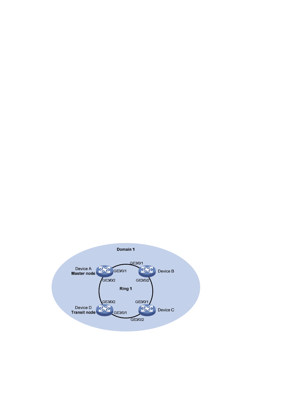
Device A, Device B, Device C, and Device D constitute RRPP domain 1, VLAN 4092 is the primary
control VLAN of RRPP domain 1, and RRPP domain 1 protects VLANs 10 through 30.
•
Device A is the master node and supports RRPP fast detection, providing a timer resolution of 10
milliseconds (which means the default Fast-Fail and Fast-Hello timers are 60 milliseconds and 20
milliseconds, respectively); Device D is a transit node; Device B and Device C do not support RRPP.
As neither Device B nor Device C supports RRPP, when the link between them fails, the link failure cannot
be detected by the master node timely. Configure RRPP fast detection to implement fast link switchover
even when the link between Device B and Device C fails.
Figure 22 Network diagram
Configuration procedure
1.
Configure Device A:
# Create VLANs 10 through 30, map these VLANs to MSTI 1, and activate MST region
configuration.