Ethernet oam configuration example, Network requirements, Configuration procedure – H3C Technologies H3C S12500 Series Switches User Manual
Page 28
17
Task Command
Remarks
Display the information about an
Ethernet OAM connection.
display oam { local | remote }
[ interface interface-type
interface-number ] [ | { begin |
exclude | include }
regular-expression ]
Available in any view.
Clear statistics on Ethernet OAM
packets and Ethernet OAM link
error events.
reset oam [ interface interface-type
interface-number ]
Available in user view only.
Ethernet OAM configuration example
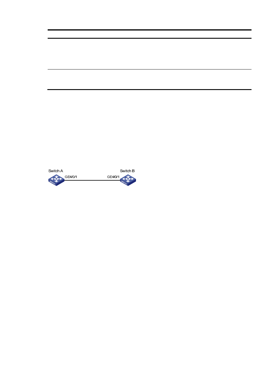
Network requirements
On the network shown in
:
•
Enable Ethernet OAM on Switch A and Switch B to auto-detect link errors between the two switches.
•
Monitor the performance of the link between Switch A and Switch B by collecting statistics about the
error frames received by Switch A.
Figure 2 Network diagram
Configuration procedure
1.
Configure Switch A:
# Configure GigabitEthernet 4/0/1 to operate in passive Ethernet OAM mode and enable
Ethernet OAM for it.
<SwitchA> system-view
[SwitchA] interface gigabitethernet 4/0/1
[SwitchA-GigabitEthernet4/0/1] oam mode passive
[SwitchA-GigabitEthernet4/0/1] oam enable
[SwitchA-GigabitEthernet4/0/1] quit
# Set the errored frame detection interval to 20 seconds and set the errored frame event triggering
threshold to 10.
[SwitchA] oam errored-frame period 20
[SwitchA] oam errored-frame threshold 10
2.
Configure Switch B:
# Configure GigabitEthernet 4/0/1 to operate in active Ethernet OAM mode (the default) and
enable Ethernet OAM for it.
<SwitchB> system-view
[SwitchB] interface gigabitethernet 4/0/1
[SwitchB-GigabitEthernet4/0/1] oam mode active
[SwitchB-GigabitEthernet4/0/1] oam enable
[SwitchB-GigabitEthernet4/0/1] quit
3.
Verify the configuration: