Network requirements, Configuration procedure – H3C Technologies H3C S12500 Series Switches User Manual
Page 222
211
The output shows that when a fault is on the link between Switch A and Switch C, the priority of
Switch A decreases to 80. Switch A becomes the backup, and Switch B becomes the master.
Packets from Host A to Host B are forwarded through Switch B.
Configuring BFD for a VRRP backup to monitor the master
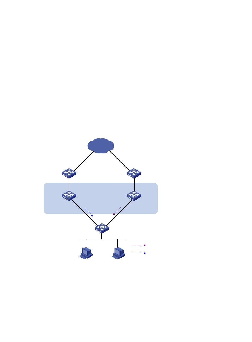
Network requirements
As shown in
, Switch A and Switch B belong to VRRP group 1, the virtual IP address of which is
192.168.0.10.
The default gateway of the hosts in the LAN is 192.168.0.10. When Switch A works correctly, the hosts
in the LAN access the external network through Switch A. When Switch A fails, the hosts in the LAN
access the external network through Switch B.
If BFD is not configured, when the master in a VRRP group fails, the backup cannot become the master
until the configured timeout timer expires. The timeout is generally 3 to 4 seconds, which makes the
switchover slow. To solve this problem, VRRP uses BFD to probe the state of the master. Once the master
fails, the backup can become the new master in milliseconds.
Figure 52 Network diagram
Configuration procedure
1.
Create VLANs, and assign corresponding ports to the VLANs, and configure the IP address of
each VLAN interface as shown in
2.
Configure VRRP on Switch A.
<SwitchA> system-view
[SwitchA] interface vlan-interface 2
Internet
Virtual router
Virtual IP address:
192.168.0.10
Vlan-int2
192.168.0.101/24
Vlan-int2
192.168.0.102/24
Switch A
Master
Switch B
Backup
L2 switch
VRRP packets
BFD probe packets