Vrrp with multiple vlans configuration example, Network requirements, Configuration procedure – H3C Technologies H3C S12500 Series Switches User Manual
Page 170
159
VRRP with multiple VLANs configuration example
Network requirements
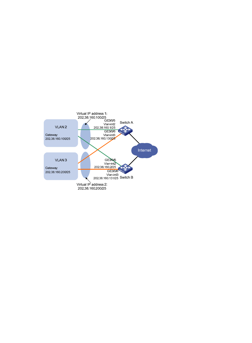
Hosts in VLAN 2 use 202.38.160.100/25 as their default gateway and hosts in VLAN 3 use
202.38.160.200/25 as their default gateway.
Switch A and Switch B belong to both VRRP group 1 and VRRP group 2. The virtual IP address of VRRP
group 1 is 202.38.160.100/25, and that of VRRP group 2 is 202.38.160.200/25.
In VRRP group 1, Switch A has a higher priority than Switch B. In VRRP group 2, Switch B has a higher
priority than Switch A. In this case, hosts in VLAN 2 and VLAN 3 can communicate with external
networks through Switch A and Switch B, respectively, and when Switch A or Switch B fails, the hosts can
use the other switch to communicate with external networks to avoid communication interruption.
Figure 41 Network diagram
Configuration procedure
1.
Configure Switch A:
# Configure VLAN 2.
<SwitchA> system-view
[SwitchA] vlan 2
[SwitchA-vlan2] port Gigabitethernet 3/0/5
[SwitchA-vlan2] quit
[SwitchA] interface vlan-interface 2
[SwitchA-Vlan-interface2] ip address 202.38.160.1 255.255.255.128
# Create a VRRP group 1 and set its virtual IP address to 202.38.160.100.
[SwitchA-Vlan-interface2] vrrp vrid 1 virtual-ip 202.38.160.100
# Configure the priority of Switch A in VRRP group 1 as 110, which is higher than that of Switch
B (100), so that Switch A can become the master in VRRP group 1.
[SwitchA-Vlan-interface2] vrrp vrid 1 priority 110
[SwitchA-Vlan-interface2] quit
# Configure VLAN 3.
[SwitchA] vlan 3
[SwitchA-vlan3] port Gigabitethernet 3/0/6