Configuration procedure – H3C Technologies H3C S12500 Series Switches User Manual
Page 237
226
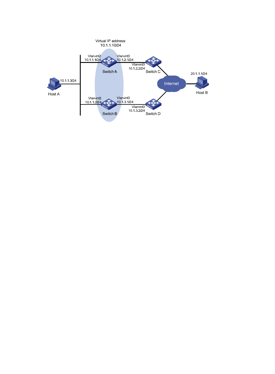
Figure 56 Network diagram
Configuration procedure
1.
Create VLANs, and assign corresponding ports to the VLANs, and configure the IP address of
each VLAN interface as shown in
2.
Configure a track entry on Switch A.
# Configure track entry 1, and associate it with the physical status of the uplink interface
VLAN-interface 3.
[SwitchA] track 1 interface vlan-interface 3
3.
Configure VRRP on Switch A.
# Create VRRP group 1, and configure the virtual IP address 10.1.1.10 for the group.
[SwitchA] interface vlan-interface 2
[SwitchA-Vlan-interface2] vrrp vrid 1 virtual-ip 10.1.1.10
# Set the priority of Switch A in VRRP group 1 to 110.
[SwitchA-Vlan-interface2] vrrp vrid 1 priority 110
# Configure to monitor track entry 1 and specify the priority decrement as 30.
[SwitchA-Vlan-interface2] vrrp vrid 1 track 1 reduced 30
4.
Configure VRRP on Switch B.
<SwitchB> system-view
[SwitchB] interface vlan-interface 2
# Create VRRP group 1, and configure the virtual IP address 10.1.1.10 for the group.
[SwitchB-Vlan-interface2] vrrp vrid 1 virtual-ip 10.1.1.10
5.
Verify the configuration.
After configuration, ping Host B on Host A, and you can see that Host B is reachable. Use the
display vrrp command to view the configuration result.
# Display detailed information about VRRP group 1 on Switch A.
[SwitchA-Vlan-interface2] display vrrp verbose
IPv4 Standby Information:
Run Mode : Standard
Run Method : Virtual MAC
Total number of virtual routers : 1