Configuration procedure – H3C Technologies H3C S12500 Series Switches User Manual
Page 173
162
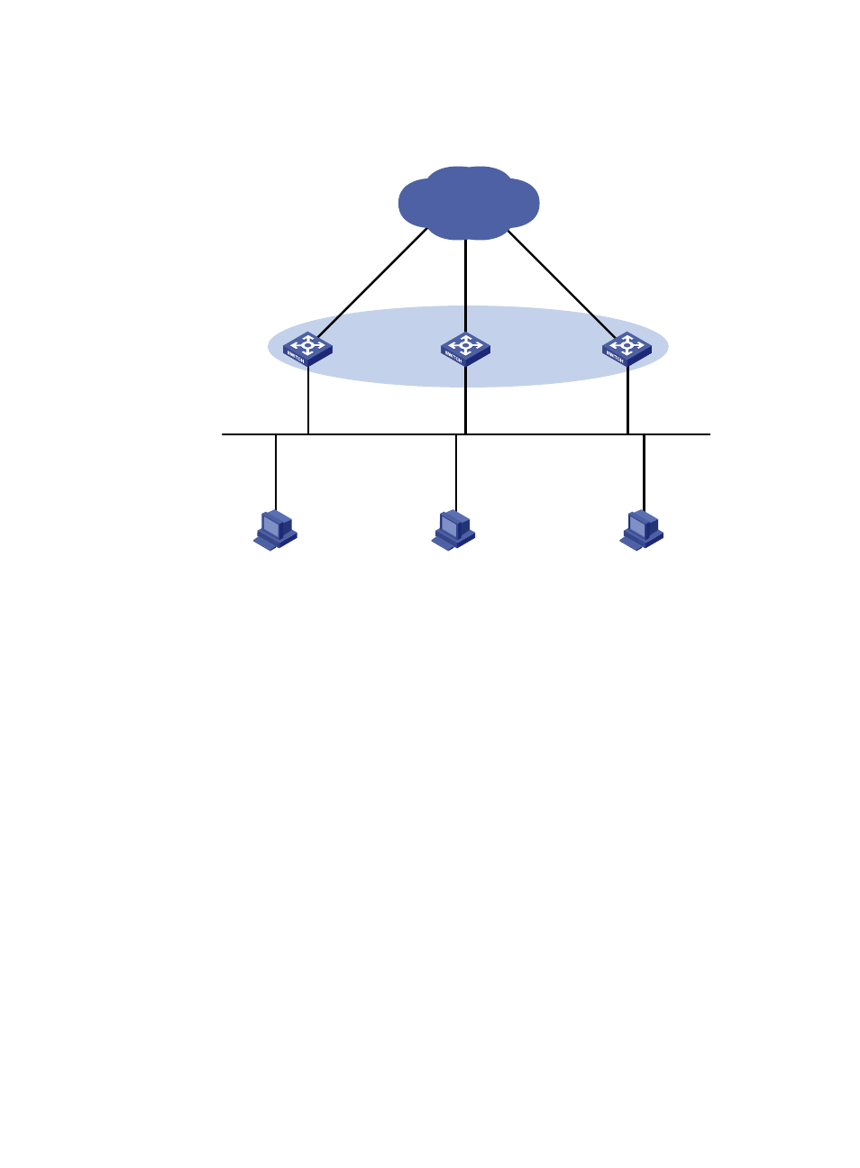
Configure track entries on Switch C to monitor Switch A and Switch B. When Switch A or Switch B fails,
Switch C immediately takes over the AVF on Switch A or Switch B.
Figure 42 Network diagram
Configuration procedure
1.
Configure Switch A:
# Configure VLAN 2.
<SwitchA> system-view
[SwitchA] vlan 2
[SwitchA-vlan2] port Gigabitethernet 3/0/5
[SwitchA-vlan2] quit
# Configure VRRP to operate in load balancing mode.
[SwitchA] vrrp mode load-balance
# Create VRRP group 1 and configure its virtual IP address as 10.1.1.1.
[SwitchA] interface vlan-interface 2
[SwitchA-Vlan-interface2] ip address 10.1.1.2 24
[SwitchA-Vlan-interface2] vrrp vrid 1 virtual-ip 10.1.1.1
# Set the priority of Switch A in VRRP group 1 to 120, which is higher than that of Switch B (110)
and that of Switch C (100), so that Switch A can become the master.
[SwitchA-Vlan-interface2] vrrp vrid 1 priority 120
# Configure Switch A to operate in preemptive mode, so that it can become the master whenever
it works correctly; configure the preemption delay as 5 seconds to avoid frequent status
switchover.
[SwitchA-Vlan-interface2] vrrp vrid 1 preempt-mode timer delay 5
[SwitchA-Vlan-interface2] quit
Host A
Host B
Host C
Switch A
Switch B
Switch C
GE3/0/5
Vlan-int2
IP: 10.1.1.2/24
VIP: 10.1.1.1/24
Network
GE3/0/5
Vlan-int2
IP: 10.1.1.3/24
VIP: 10.1.1.1/24
GE3/0/5
Vlan-int2
IP: 10.1.1.4/24
VIP: 10.1.1.1/24
Master
AVF 1
Backup
AVF 2
Backup
AVF 3
IP: 10.1.1.5/24
Gateway IP: 10.1.1.1/24
IP: 10.1.1.6/24
Gateway IP: 10.1.1.1/24
IP: 10.1.1.7/24
Gateway IP: 10.1.1.1/24
Vlan-int3
Vlan-int3
Vlan-int3