Dual homed rings, Single-ring load balancing, N in – H3C Technologies H3C S12500 Series Switches User Manual
Page 73: Figure 15, Figure 14
62
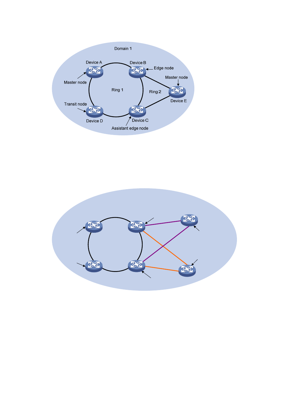
Figure 14 Schematic diagram for an intersecting-ring network
Dual homed rings
As shown in
, two or more rings are in the network topology and two similar common nodes
exist between rings. You only need to define an RRPP domain, and configure one ring as the primary ring
and the other rings as subrings.
Figure 15 Schematic diagram for a dual-homed-ring network
Single-ring load balancing
In a single-ring network, you can achieve load balancing by configuring multiple domains.
As shown in
, Ring 1 is configured as the primary ring of both Domain 1 and Domain 2.
Domain 1 and Domain 2 are configured with different protected VLANs. In Domain 1, Device A is
configured as the master node of Ring 1; in Domain 2, Device B is configured as the master node of Ring
1. Such configurations enable the ring to block different links based on VLANs and achieve single-ring
load balancing.
Device A
Device B
Device C
Device D
Device E
Edge node
Master node
Transit node
Assistant edge node
Domain 1
Ring 1
Ring 2
Master node
Device F
Master node
Ring 3