Dual homed rings configuration example, Networking requirements – H3C Technologies H3C S12500 Series Switches User Manual
Page 92
81
Dual homed rings configuration example
Networking requirements
As shown in
,
•
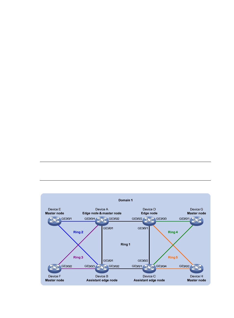
Device A through Device H form RRPP domain 1. Specify the primary control VLAN of RRPP domain
1 as VLAN 4092, and specify that RRPP domain 1 protects VLANs 1 through 30.
•
Device A through Device D form primary ring 1. Device A, Device B, and Device E form subring 2.
Device A, Device B, and Device F form subring 3. Device C, Device D, and Device G form subring
4. Device C, Device D, and Device H form subring 5.
Specify Device A as the master node of primary ring 1, GigabitEthernet 3/0/1 as the primary port and
GigabitEthernet 3/0/2 as the secondary port. Specify Device E as the master node of subring 2,
GigabitEthernet 3/0/1 as the primary port and GigabitEthernet 3/0/2 as the secondary port. Specify
Device F as the master node of subring 3, GigabitEthernet 3/0/1 as the primary port and
GigabitEthernet 3/0/2 as the secondary port. Specify Device G as the master node of subring 4,
GigabitEthernet 3/0/1 as the primary port and GigabitEthernet 3/0/2 as the secondary port. Specify
Device H as the master node of subring 5, GigabitEthernet 3/0/1 as the primary port and
GigabitEthernet 3/0/2 as the secondary port.
Specify Device A as the edge node of the connected subrings, its GigabitEthernet 3/0/3 and
GigabitEthernet 3/0/4 as the edge ports. Specify Device D as the transit node of the primary ring and
edge node of the connected subrings, its GigabitEthernet 3/0/3 and GigabitEthernet 3/0/4 as the
edge ports. Specify Device B and Device C as the transit node of the primary ring and assistant-edge
nodes of the connected subrings, their GigabitEthernet 3/0/3 and GigabitEthernet 3/0/4 as the edge
ports.
NOTE:
Configure the primary and secondary ports on the master nodes correctly to make sure other protocols still
work correctly when data VLANs are denied by the secondary ports.
Figure 20 Network diagram
G
E3
/0/2
GE3/
0/1
G
E3/
0/1
GE3/0
/2
GE3/0/3
GE3/0/4
G
E3/
0/4
GE3/0/3