Configuration procedure – H3C Technologies H3C S12500 Series Switches User Manual
Page 127
116
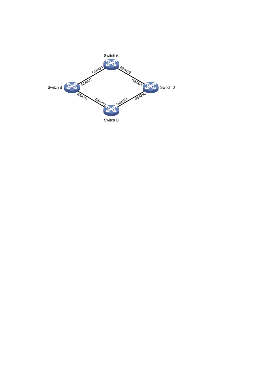
Implement dual uplink backup and load sharing on Switch C: traffic of VLANs 1 through 100 is uplinked
to Switch A by Switch B; traffic of VLANs 101 through 200 is uplinked to Switch A by Switch D.
Figure 25 Network diagram
Configuration procedure
1.
Configure Device C:
# Create VLAN 1 through VLAN 200, map VLANs 1 through 100 to MSTI 1, and VLANs 101
through 200 to MSTI 2, and activate MST region configuration.
<SwitchC> system-view
[SwitchC] vlan 1 to 200
[SwitchC] stp region-configuration
[SwitchC-mst-region] instance 1 vlan 1 to 100
[SwitchC-mst-region] instance 2 vlan 101 to 200
[SwitchC-mst-region] active region-configuration
[SwitchC-mst-region] quit
# Shut down GigabitEthernet 4/0/1 and GigabitEthernet 4/0/2, disable the spanning tree
feature on GigabitEthernet 4/0/1 and GigabitEthernet 4/0/2 separately, configure the ports as
trunk ports, and assign them to VLAN 1 through VLAN 200.
[SwitchC] interface gigabitethernet 4/0/1
[SwitchC-GigabitEthernet4/0/1] shutdown
[SwitchC-GigabitEthernet4/0/1] undo stp enable
[SwitchC-GigabitEthernet4/0/1] port link-type trunk
[SwitchC-GigabitEthernet4/0/1] port trunk permit vlan 1 to 200
[SwitchC-GigabitEthernet4/0/1] quit
[SwitchC] interface gigabitethernet 4/0/2
[SwitchC-GigabitEthernet4/0/2] shutdown
[SwitchC-GigabitEthernet4/0/2] undo stp enable
[SwitchC-GigabitEthernet4/0/2] port link-type trunk
[SwitchC-GigabitEthernet4/0/2] port trunk permit vlan 1 to 200
[SwitchC-GigabitEthernet4/0/2] quit
# Create smart link group 1, and configure all VLANs mapped to MSTI 1 as the protected VLANs
for smart link group 1.
[SwitchC] smart-link group 1
[SwitchC-smlk-group1] protected-vlan reference-instance 1