Configuration procedure – H3C Technologies H3C S12500 Series Switches User Manual
Page 190
179
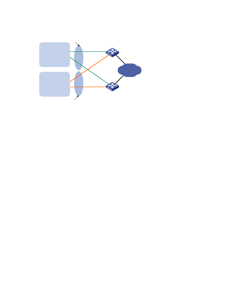
Figure 45 Network diagram
Configuration procedure
1.
Configure Switch A:
# Configure VLAN 2.
<SwitchA> system-view
[SwitchA] ipv6
[SwitchA] vlan 2
[SwitchA-vlan2] port Gigabitethernet 3/0/5
[SwitchA-vlan2] quit
[SwitchA] interface vlan-interface 2
[SwitchA-Vlan-interface2] ipv6 address fe80::1 link-local
[SwitchA-Vlan-interface2] ipv6 address 1::1 64
# Create VRRP group 1 and set its virtual IPv6 addresses to FE80::10 to 1::10.
[SwitchA-Vlan-interface2] vrrp ipv6 vrid 1 virtual-ip fe80::10 link-local
[SwitchA-Vlan-interface2] vrrp ipv6 vrid 1 virtual-ip 1::10
# Set the priority of Switch A in VRRP group 1 to 110, which is higher than that of Switch B (100),
so that Switch A can become the master in VRRP group 1.
[SwitchA-Vlan-interface2] vrrp ipv6 vrid 1 priority 110
[SwitchA-Vlan-interface2] quit
# Enable Switch A to send RA messages, so that hosts in VLAN 2 can learn the default gateway
address.
[SwitchA-Vlan-interface2] undo ipv6 nd ra halt
[SwitchA-Vlan-interface2] quit
# Configure VLAN 3.
[SwitchA] vlan 3
[SwitchA-vlan3] port Gigabitethernet 3/0/6
[SwitchA-vlan3] quit
[SwitchA] interface vlan-interface 3
[SwitchA-Vlan-interface3] ipv6 address fe90::1 link-local
[SwitchA-Vlan-interface3] ipv6 address 2::1 64
Switch A
Switch B
Virtual IPv6 address 1:
FE80::10
1::10/64
Virtual IPv6 address 2:
FE90::10
2::10/64
GE3/0/5
Vlan-int2
FE80::1
1::1/64
GE3/0/5
Vlan-int2
FE80::2
1::2/64
Internet
VLAN 2
Gateway: 1::10/64
VLAN 3
Gateway: 2::10/64
GE3/0/6
Vlan-int3
FE90::1
2::1/64
GE3/0/6
Vlan-int3
FE90::2
2::2/64