Vrrp load balancing mode, Overview, N in – H3C Technologies H3C S12500 Series Switches User Manual
Page 145: Figure 34
134
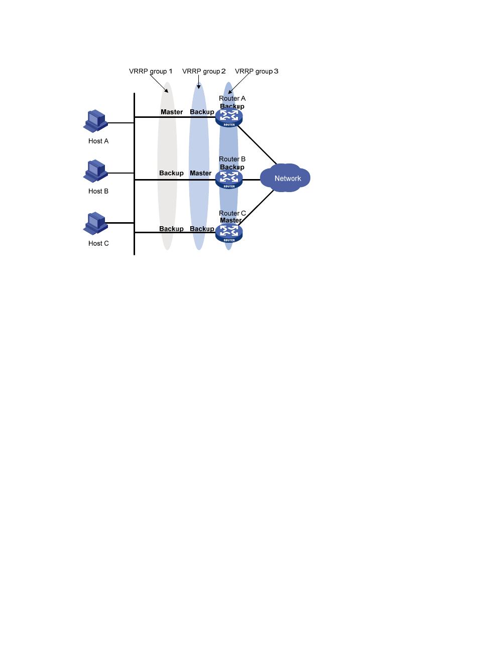
Figure 34 VRRP in load sharing mode
A router can be in multiple VRRP groups and hold a different priority in a different group.
As shown in
, the following VRRP groups are present:
•
VRRP group 1—Router A is the master; Router B and Router C are the backups.
•
VRRP group 2—Router B is the master; Router A and Router C are the backups.
•
VRRP group 3—Router C is the master; Router A and Router B are the backups.
For load sharing among Router A, Router B, and Router C, hosts on the LAN need to be configured to use
VRRP group 1, 2, and 3 as the default gateways. When you configure VRRP priorities, make sure that
each router holds such a priority in each VRRP group that it will take the expected role in the group.
VRRP load balancing mode
Overview
In a standard-mode VRRP group, only the master can forward packets and the backups are in listening
state. You can create multiple VRRP groups to share load, but must assign different gateways to the hosts
on the LAN.
Load balancing mode simplifies configuration and improves forwarding efficiency. In load balancing
mode, a VRRP group maps its virtual IP address to multiple virtual MAC addresses: one virtual MAC
address for each group member. The master uses these virtual MAC addresses of the member routers to
respond to IPv4 ARP requests or IPv6 ND requests from hosts. Therefore, every router in this VRRP group
can forward traffic and traffic from hosts is distributed across the VRRP group members.
VRRP load balancing mode is based on VRRP standard protocol mode, so mechanisms, such as master
election, preemption, and tracking functions, in the standard protocol mode are also supported in the
load balancing mode. In addition, VRRP load balancing mode has new mechanisms, which are
introduced in the following sections.