Configuration procedure, N in, Figure 27 – H3C Technologies H3C S12500 Series Switches User Manual
Page 134
123
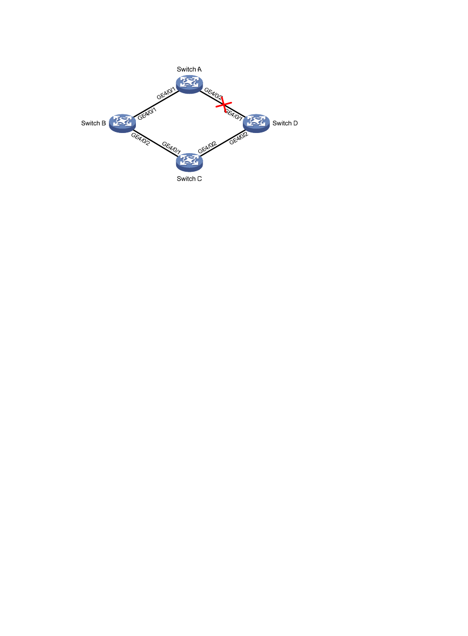
Figure 27 Network diagram
Configuration procedure
1.
Configure Switch C:
# Create VLANs 1 through 30, map these VLANs to MSTI 1, and activate MST region
configuration.
<SwitchC> system-view
[SwitchC] vlan 1 to 30
[SwitchC] stp region-configuration
[SwitchC-mst-region] instance 1 vlan 1 to 30
[SwitchC-mst-region] active region-configuration
[SwitchC-mst-region] quit
# Shut down GigabitEthernet 4/0/1 and GigabitEthernet 4/0/2, and disable the spanning tree
feature on them. Configure the two ports as trunk ports, and assign them to VLANs 1 through 30.
[SwitchC] interface GigabitEthernet 4/0/1
[SwitchC-GigabitEthernet4/0/1] shutdown
[SwitchC-GigabitEthernet4/0/1] undo stp enable
[SwitchC-GigabitEthernet4/0/1] port link-type trunk
[SwitchC-GigabitEthernet4/0/1] port trunk permit vlan 1 to 30
[SwitchC-GigabitEthernet4/0/1] quit
[SwitchC] interface GigabitEthernet 4/0/2
[SwitchC-GigabitEthernet4/0/2] shutdown
[SwitchC-GigabitEthernet4/0/2] undo stp enable
[SwitchC-GigabitEthernet4/0/2] port link-type trunk
[SwitchC-GigabitEthernet4/0/2] port trunk permit vlan 1 to 30
[SwitchC-GigabitEthernet4/0/2] quit
# Create smart link group 1, and configure all the VLANs mapped to MSTI 1 as the protected
VLANs for smart link group 1.
[SwitchC] smart-link group 1
[SwitchC-smlk-group1] protected-vlan reference-instance 1
# Configure GigabitEthernet 4/0/1 as the master port and GigabitEthernet 4/0/2 as the slave
port for smart link group 1.
[SwitchC-smlk-group1] port GigabitEthernet 4/0/1 master
[SwitchC-smlk-group1] port GigabitEthernet 4/0/2 slave
# Enable the smart link group to transmit flush messages.