Vrrp load balancing mode configuration example, Network requirements, Configuration procedure – H3C Technologies H3C S12500 Series Switches User Manual
Page 193
182
The output shows that in VRRP group 1 Switch A is the master, Switch B is the backup and hosts
with the default gateway of 1::10/64 accesses the Internet through Switch A; in VRRP group 2
Switch A is the backup, Switch B is the master and hosts with the default gateway of 2::10/64
accesses the Internet through Switch B.
NOTE:
Multiple VRRP groups are commonly used in actual networking. In an IPv6 network, to implement load
sharing among multiple VRRP groups, manually configure the default gateway for hosts.
VRRP load balancing mode configuration example
Network requirements
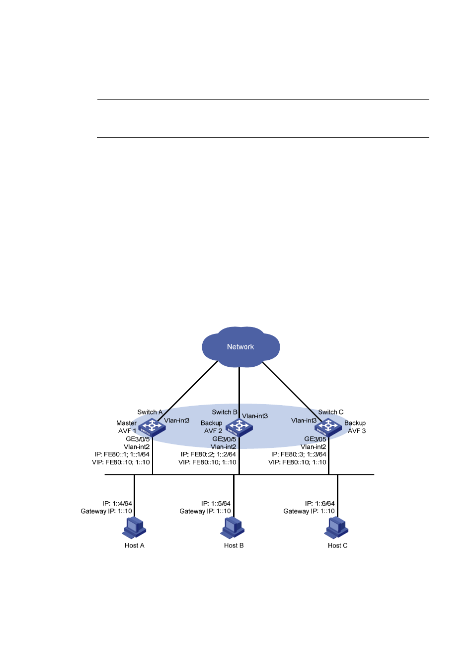
Switch A, Switch B, and Switch C belong to VRRP group 1 with the virtual IPv6 addresses of FE80::10 and
1::10.
Hosts on network segment 1::/64 learn 1::10 as their default gateway through RA messages sent by the
switches. Use the VRRP group to make sure that when a gateway (Switch A, Switch B, or Switch C) fails,
the hosts on the LAN can access the external network through another gateway.
VRRP group 1 is operating in load balancing mode to make good use of network resources.
Configure a track entry on Switch A, Switch B, and Switch C to monitor their own VLAN-interface 3.
When the interface on Switch A, Switch B, or Switch C fails, the weight of the corresponding switch
decreases so that another switch with a higher weight can take over.
Figure 46 Network diagram
Configuration procedure
1.
Configure Switch A: