Error code troubleshooting – 3 of 4 -17 – Hypertherm HD4070 Rev.1 User Manual
Page 180
HyPerformance H
D4
0
70
Instruction Manual
5-17
MAINTENANCE
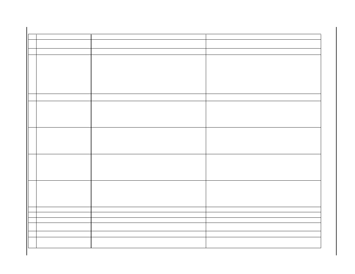
Error code troubleshooting – 3 of 4
ID #
Error Code or Message
Description
Corrective action
1 0 2 CURRENT BEFORE IGNITION
Current detected from choppers before ignition.
(1) Verify wiring from control PCB to choppers. (2) Check LED - D7 on
control board, it should be off.
1 0 8 TRANSFER BEFORE IGNITION
Current detected at sensor before start signal
(1) Check wires between sensor and control board. (2) Replace sensor
1 0 9 COOLANT FLOW SENSOR FAIL
When the power supply is turned on, the system checks operation of the
coolant flow sensor. This error is activated if the flow sensor detects coolant
flow before the coolant pump has been turned on.
(1) If the plasma interface board LED D17 is ON (indicating coolant flow),
check for continuity across coolant flow sensor output connections. If there is
continuity across the sensor output connections, replace the sensor. If LED
D17 is ON and there is no continuity across the sensor output connections,
troubleshoot the plasma interface board. (2) If the plasma interface board
LED D17 is OFF (indicating no coolant flow), check that the breakout board
LEDN 3-5 is ON (indicating coolant flow). If LEDN 3-5 is ON, with no coolant
flow, trouble shoot the breakout board. (3) If the breakout board LEDN 3-5 is
OFF (indicating no coolant flow), check output signal from breakout board J-11,
Pin 35, to B4-J4, pin 35, on PC-104. (4) Use the PC-104 test software and
test board to verify the proper operation of PC-104 board B4.
1 1 1 COOLANT OVERTEMP
Coolant temperature sensor indicates high coolant temperature before the
coolant pump has been turned on.
Trouble shoot coolant temperature switch.
1 1 2 CABLE CHECK A FAIL
When the power supply is turned on, the system checks ribbon cable
connections between the PC-104 and the breakout board and for the proper
operation of the PC-104 digital I/O boards. A digital output from the PC-104 is
connected through one ribbon cable to the breakout board and is returned
through a second cable to an analog input on the PC-104. This error is
activated if the test circuit has open continuity or if the PC-104 digital I/O
boards do not operate properly.
(1) Check that ribbon cable is properly installed from PC-104 connector B5-J1
to breakout board connector J8. (2) Check that ribbon cable is properly
installed from PC-104 connector B4-J1 to breakout board connector J11. (3)
Use an Ohm meter to check crimp terminations and individual connections on
each of the ribbon cables. (4) Verify continuity between the breakout board
connectors J8-19 and J5-11. If no continuity, replace breakout board. (5)
Use the PC-104 test software and test board to verify the proper operation of
PC-104 boards B4 and B5.
1 1 3 CABLE CHECK B FAIL
When the power supply is turned on, the system checks ribbon cable
connections between the PC-104 and the breakout board and for the proper
operation of the PC-104 digital I/O boards. A digital output from the PC-104 is
connected through one ribbon cable to the breakout board and is returned
through a second cable to an analog input on the PC-104. This error is
activated if the test circuit has open continuity or if the PC-104 digital I/O
boards do not operate properly.
(1) Check that ribbon cable is properly installed from PC-104 connector B5-J1
to breakout board connector J8. (2) Check that ribbon cable is properly
installed from PC-104 connector B5-J4 to breakout board connector J6. (3)
Use an Ohm meter to check crimp terminations and individual connections on
each of the ribbon cables. (4) Verify continuity between the breakout board
connectors J8-33 and J6-17. If no continuity, replace breakout board. (5)
Use the PC-104 test software and test board to verify the proper operation of
PC-104 board B5.
1 1 4 CABLE CHECK C FAIL
When the power supply is turned on, the system checks ribbon cable
connections between the PC-104 and the breakout board and for the proper
operation of the PC-104 digital I/O boards. A digital output from the PC-104 is
connected through one ribbon cable to the breakout board and is returned
through a second cable to an analog input on the PC-104. This error is
activated if the test circuit has open continuity or if the PC-104 digital I/O
boards do not operate properly.
(1) Check that ribbon cable is properly installed from PC-104 connector B4-J4
to breakout board connector J15. (2) Check that ribbon cable is properly
installed from PC-104 connector B4-J1 to breakout board connector J11. (3)
Use an Ohm meter to check crimp terminations and individual connections on
each of the ribbon cables. (4) Verify continuity between the breakout board
connectors J15-37 and J11-7. If no continuity, replace breakout board. (5)
Use the PC-104 test software and test board to verify proper operation of PC-
104 board B4.
1 1 5 ANALOG TEST FAIL
When the power supply is turned on, the system checks ribbon cable
connections between the PC-104 and the breakout board and for the proper
operation of the PC-104 board B6. A digital output from the PC-104 is
connected through one ribbon cable to the breakout board and is returned
through a second cable to an analog input on the PC-104. This error is
activated if the test circuit has open continuity or if the PC-104 board B6 does
not operate properly.
(1) Check that ribbon cable is properly installed from PC-104 connector B5-J1
to breakout board connector J5. (2) Check that ribbon cable is properly
installed from PC-104 connector B6-J1 to breakout board connector J5. (3)
Use an Ohm meter to check crimp terminations and individual connections on
each of the ribbon cables. (4) Verify continuity between the breakout board
connectors J8-19 and J5-11. If no continuity, replace breakout board. (5) Use
the PC-104 test software and test board to verify proper operation of PC-104
boards B5 and B6.
1 1 6 WATCHDOG TIMEOUT
watchdog on breakout board (PCB6)not satisfied.
Check external interlocks.
1 1 7 THC CONTROL FAI
L
I
ndicates a failure on the THC control board.
Replace board.
1 1 8 THC LIFTER NOT DETECTED
Cable not connected or damaged.
(1) Install cable. (2) Check cables and connections
1 2 0
THC PLASMA CABLE NOT
DETECTED
Cable not connected or damaged.
(1) Install cable. (2) Check cables and connections
1 2 1 THC COMM FAIL
Plasma system is unable to communicate with the THC.
(1) No power to THC, check power supply. (2) Check cables and
connections.
1 2 2 GAS COMM FAIL
Gas control cable disconnected, Gas console power cable disconnected. Gas
console control board failure, PC104 dual serial board failure or Breakout board
failure.
(1) Make sure cables are present and properly connected. (2) Verify that gas
console has power. (3) Look for activity on the indicator LED's on the
breakout board.