Hypertherm HD4070 Rev.1 User Manual
Page 202
HyPerformance HD4070
Instruction Manual
5-39
MAINTENANCE
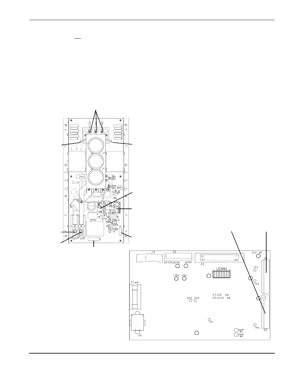
6. If a chopper does not output +311 VDC, check to see if LED1 logic power light is illuminated. If LED1 is
extinguished, check if 120V is going to JP6. If there is no 120V at JP6, check wiring back to power distribution
board. Repair or replace any defective components. Also check to see if LED3 is turning green when start
command is given (normal condition). If LED1 is illuminated and LED3 is red when start signal is given (fault
condition), then make sure that JP9 is seated properly. Check wiring from JP9 to control board. Replace control
board if necessary.
7. If a chopper still does not output +311 VDC after completing these instructions through step 6, there may be a
problem with the control signal or the chopper module. The chopper drive signal comes through the control
board PCB3 as an analog level from 0 to +3.5 VDC, which varies the duty cycle and subsequent output current
of the chopper. These analog signals are on PCB3, J4, pins 11&12 for CH1 and J5, pins 11&12 for CH2.
D13
D14
D12
D6
D5
D3
D2
D1
D4
D7
D9
Control board – PCB3
J4
J5
Chopper module – front view
JP6
LED3
JP9
LED1
Bridge (–)
Bridge (+)
(-) TORCH
(+) WORK
3 phase input