Figure 4: unit port configuration – NavCom StarUtil Rev.E User Manual
Page 11
STARUTIL User Guide Rev. E
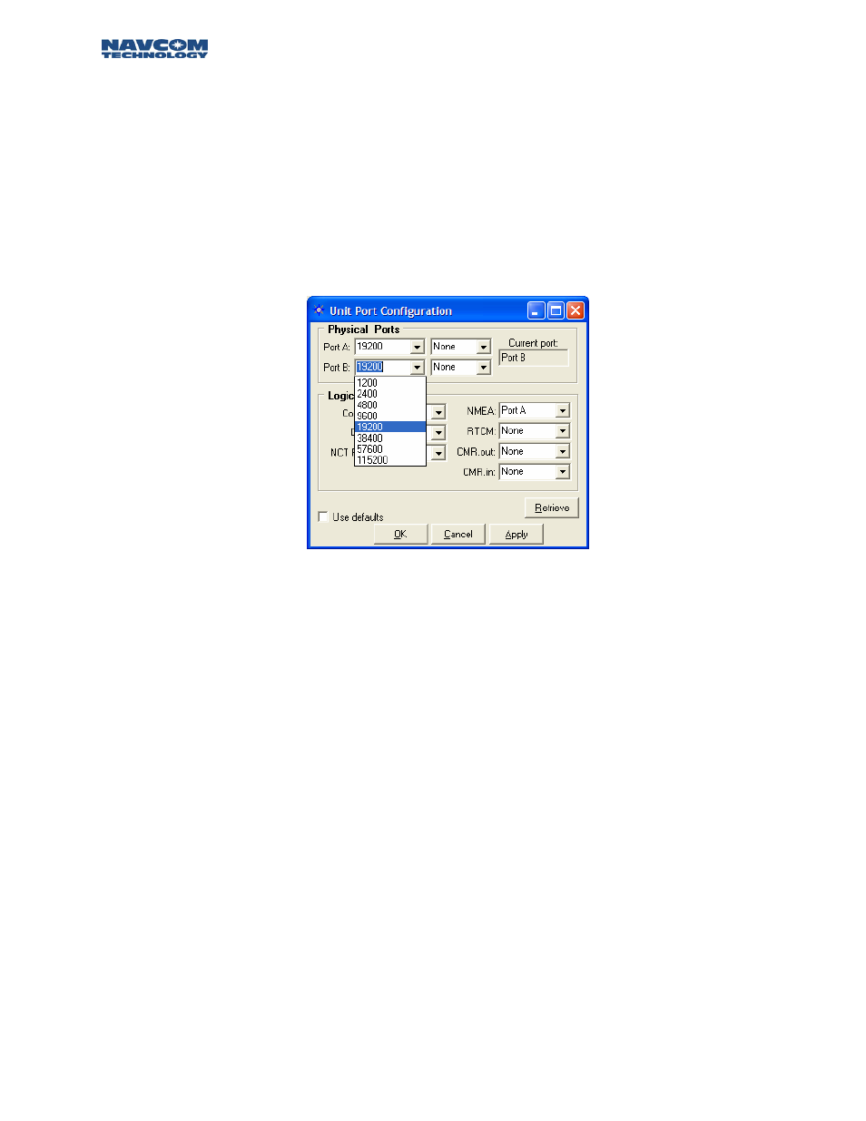
Now that PC Port Configuration has been established, the receiver must have its logical ports setup
to meet the specific requirements of the application. At this point you may choose to change the
Control Port to Com 1, elect an output port for NMEA, or an input port for the correction
information being received from an external source. The Unit Port Configuration screen can be
reached by pressing the Ports icon on the Toolbar, or from the Menu Bar pressing
RECEIVER\SETUP\PORTS. Figure 4 shows a typical Unit Port Configuration used for outputting
NMEA data via the Data Port [Port A/Com 1], controlling the receiver via Com 2 [Port B], and
receiving RTK corrections via the *internal radio. The Physical Ports area of Figure 4 displays the
baud rate, and parity at which the port communicates to the Controller Solution.
*
Internal radio option available on the RT-3010 & RT-3020 models only.
Figure 4: Unit Port Configuration
The Default Settings of the Physical Ports is set to 19200. The baud rate can be changed by simply
clicking on the pull-down menu for port A and B and selecting any of the predetermined baud rates
as shown in Figure 4.
The default logical physical mapping places the Control in the Current Port B, and Data, & NMEA,
in the Non-Current Port A. The logical physical mapping of ports can be changed by clicking on any
port and the pull-down menu shown in Figure 4. Logically, there are six ports and physically there
are two, Port A [Com1], and B [Com 2]. The six logical ports are Control, Data, NCT RTK, NMEA,
RTCM, and CMR as shown in Figure 4. Control and NCT RTK are very similar and work with
proprietary messages. The RTCM port receives differential corrections as a rover, and sends out
RTCM 104 corrections if the receiver has been set up as a base station; the CMR port operates in
similar fashion. The NMEA port communicates messages using a protocol for communications
between marine instrumentation. This interface permits flexibility in communication and control of
the various message streams.
The “Apply” button sends the changes to the receiver, and will store the values in NVRam for
recovery after a power cycle. The “Retrieve” button will send a request to the
receiver for the
information stored in NV-Ram pertinent to this particular display. These two buttons operate as
described for each window in which they appear. Checking the Use Defaults box will apply the
factory default configuration for both Physical and Logical Ports.
2 – 10