Figure 23: output correction types, Figure 24: setup base location; user input, Figure 25: setup base location; self-survey – NavCom StarUtil Rev.E User Manual
Page 26
STARUTIL User Guide Rev. E
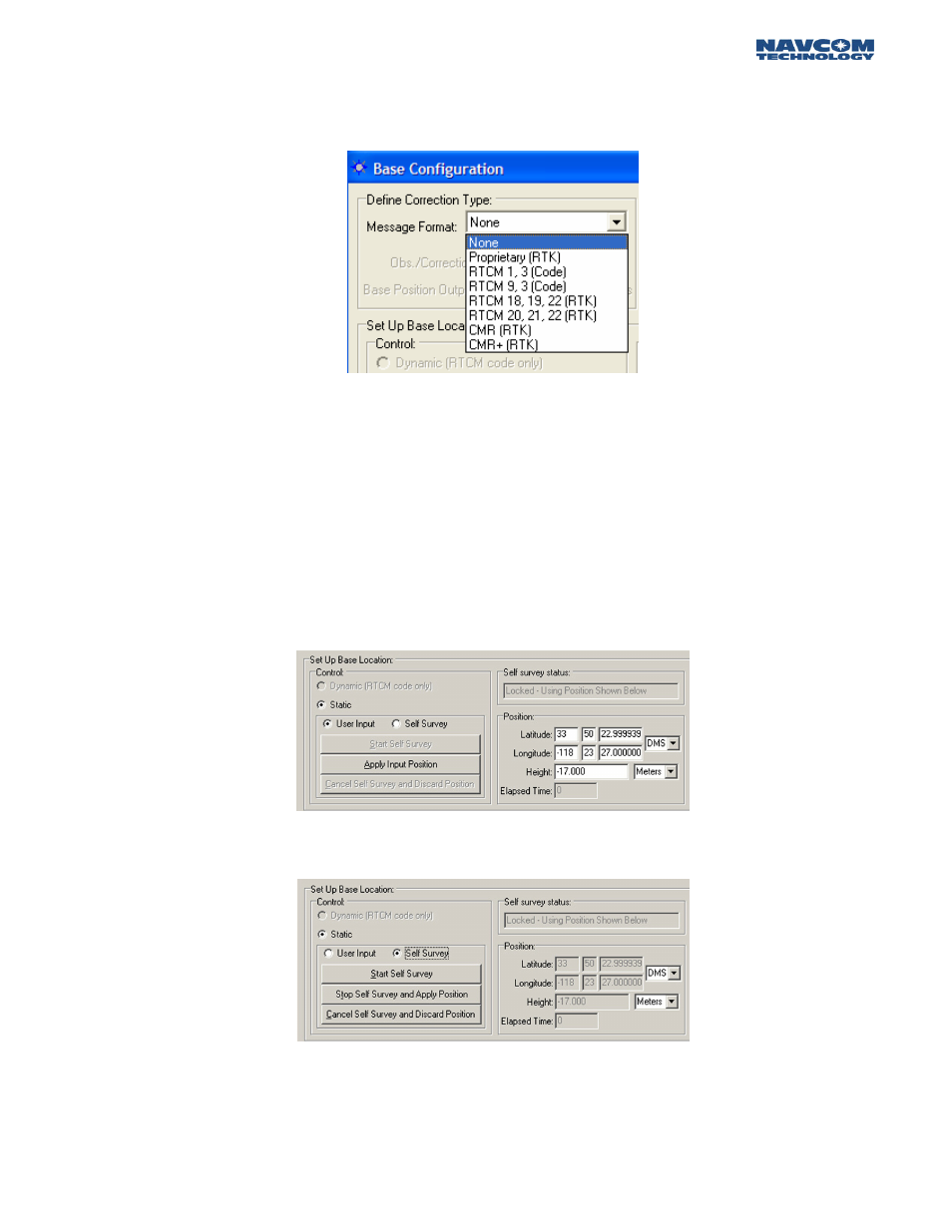
In the Define Correction Type area of Figure 23, you will choose the corrections that are required for
output, the Correction Output Rate, and the Base Position Output Rate. In this instance you will
choose Proprietary RTK. Figure 24 shows the available correction types the receiver can transmit.
Figure 24: Output Correction Types
In the RTK Base Control area of this window you will choose an Elevation Mask, and a Base Station
Site ID. The Unit Port Configuration button in this screen brings up the window described in
Chapter 2 Figure 4 set to the default parameters, and the Antenna Setup button brings up the
window described in Chapter 3 Figure 16.
The Setup Base Location area of the Base Configuration window allows the user to manually enter a
Base position, for which corrections will be generated, or have the receiver automatically generate a
position relative to phase positions collected and averaged over a period of time. Figure 25 & 26
show what this area will look like when “User Input” or “Self Survey” is enabled.
Figure 25: Setup Base Location; User Input
Figure 26: Setup Base Location; Self-Survey
The user must enter a Base Location through one of the modes described before output of valid
corrections can commence.
4 - 23