Figure 30: rtk base message output list – NavCom StarUtil Rev.E User Manual
Page 29
STARUTIL User Guide Rev. E
Press the Base Icon on the StarUtil main window, and Figure 23 will appear. This is the Base
Configuration window, where the majority of controls are that will enable the receiver to operate as
a Base Station.
In the Define Correction Type area of Figure 23, you will choose the corrections that are required for
output, the Correction Output Rate, and the Base Position Output Rate. In this instance you will
choose Proprietary RTK. Figure 24 shows the available correction types the receiver can output.
In the RTK Base Control area of this window you will choose an Elevation Mask, and a Base Station
Site ID. The Unit Port Configuration button brings up the window described in Chapter 2 Figure 4,
and Antenna Setup brings up the window described in Chapter 3 Figure 16. The Unit Port
Configuration window may open set to the default parameters. At this point you should direct the
NCT RTK corrections to an external port for output. If the NCT RTK port is not set to A or B [any
port other than the Control Port, Port Radio, or NONE], change the NCT RTK port to the opposite
of the Control Port, i.e. Control is B (default) then NCT RTK will be A, and press “Apply”. Connect
the output port cable to the external radio; you should now have corrections sent out over the
external radio link.
The Setup Base Location area of the Base Configuration window allows the user to manually enter a
Base position, for which corrections will be generated, or have the receiver automatically generate a
position relative to phase positions collected and averaged over a period of time. Figure 25 & 26
shows what this area will look like when User Input or Self Survey is enabled. The user must enter a
Base Location through one of the modes described so the output of valid corrections can
commence.
RTCM, CMR+, and CMR Base Stations are setup in the same manner as the Proprietary RTK output.
After choosing your dGPS format, the appropriate areas of the Base Configuration window will
become active. As with the example above, provide the necessary information, and click “Apply” or
“OK” to have your changes preserved in the receiver. An additional step is required to output these
formats; in the Unit Port Configuration window in Figure 30, the user must choose the port the
dGPS corrections will be output to.
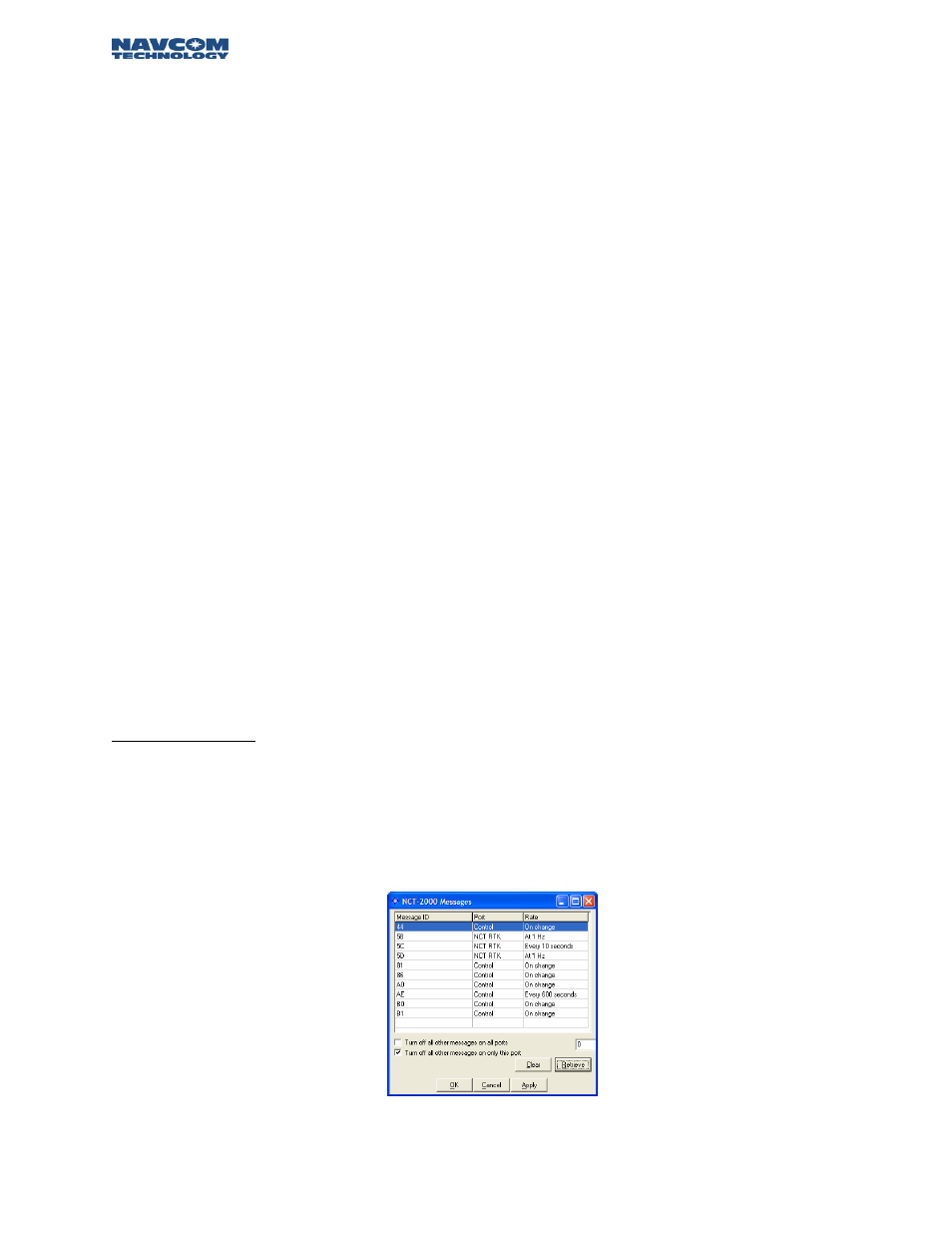
RTK Extend Users:
An additional message must be transmitted over your external radio link in order to enable the RTK
Extend feature in the Rover. Follow the procedure in Chapter 3 Navigation & Data Output
Configuration, to enable the 0x5D message. The 5D message rate should be “On Change”, and the
Output port will be the same as is configured for the 0x5B and 0x5C messages. Figures 6 – 10 detail
just how to accomplish this. After completing all actions, your NCT Messages window will appear as
shown in Figure 31.
Figure 31: RTK Base Message Output List
4 – 26