Chapter 9 1pps/events, Figure 54: 1 pps & events location, Figure 55: 1 pps & event latch configuration – NavCom StarUtil Rev.E User Manual
Page 46
STARUTIL User Guide Rev. E
Chapter 9
1PPS/Events
The 1 PPS output pulse output from the receiver is synchronized with GPS time, and is shaped as
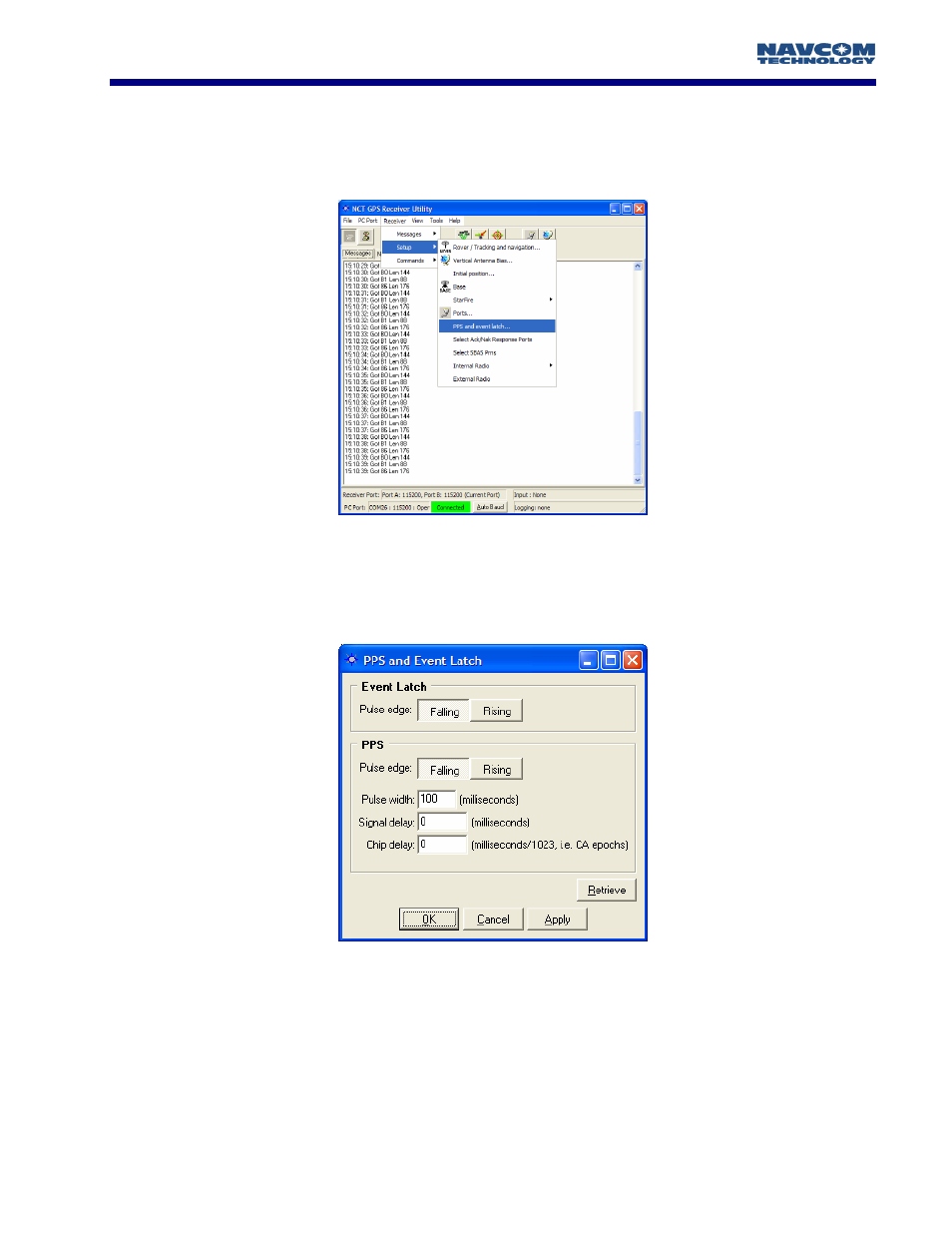
described in Words 1 through 6 of NCT Binary Message 0x16. To get to the control window, from
the main StarUtil window click RECEIVER\SETUP\PPS AND EVENT LATCH as shown in Figure 55.
Figure 55: 1 PPS & Events Location
Once here you can shape the characteristics of the 1 PPS pulse to suit your application
requirements, see Figure 56. The user allowable adjustment limits of the pulse are shown below and
detailed in the Technical Reference Manual (TRM).
Figure 56: 1 PPS & Event Latch Configuration
The Events Input can be triggered on the Falling, or Rising edge of the input pulse. The Event Latch
message (0xB4) must be enabled in the NCT Message Output list shown in Figure 7 of Chapter 3;
however the Message Rate for the 0xB4 must be set to “On Trigger”. The “On Trigger” message
rate can be located by Right- Clicking on the Rate area adjacent to the B4 Message ID, and
following the menus as seen in Figure 57. The Event Latch Message 0xB4 will only be output when
the chosen pulse edge of the incoming event is sensed by the receiver.
9 - 43