2ru panels, Tutorials – Grass Valley NVISION Compact CQX User Manual
Page 103
Compact Router System Configurator • User’s Guide
91
12. Tutorials
Products
2RU Panels
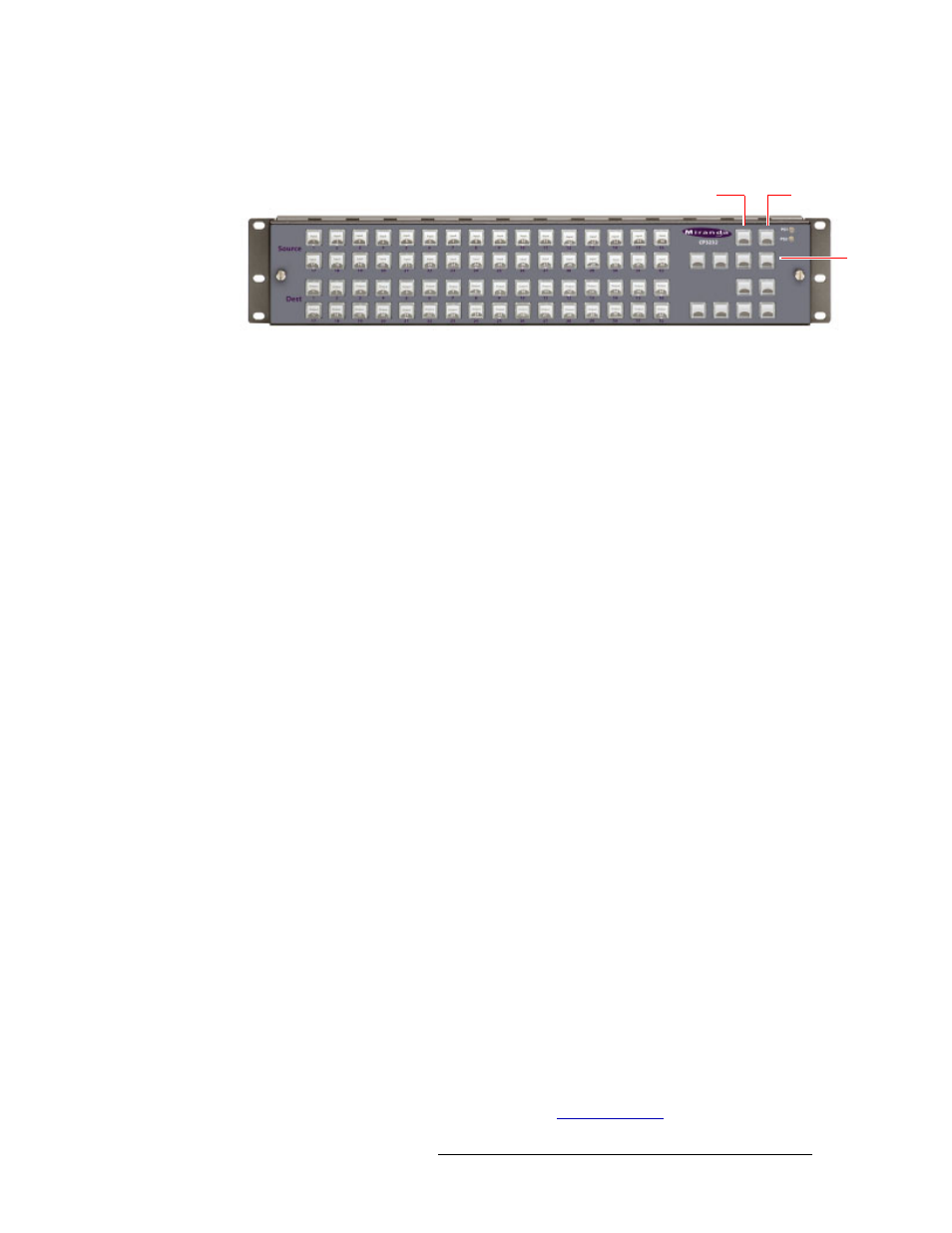
The CP3232 control panel has 76 buttons:
Figure 12-26. Front view of the CP3232 Control Panel
The CP3204 control panel resembles the CP3232, but it has 4 buttons in the lower section on the
left, instead of 32.
In stand-alone systems, a CP3232 has 32 source selection buttons, 32 destination selection buttons,
the 2 lock buttons shown, and 4 level selection buttons (as shown).
In a Compact Router Series system, all buttons except the lock buttons (shown) are configurable. In
an NV9000 system, all buttons are configurable, including the lock buttons.
You can mount a 2RU panel on any 2RU router or remote panel module.
Except under NV9000 control, all control panels have two lock buttons (at the top right):
• Panel Lock. Protects the state of the entire panel.
• Destination Lock. Protects one or more destinations.
Buttons are not labeled at the factory. If you want button legends, you must create your own.
A panel’s buttons have color: green, amber, red. In a Compact Router Series system, the colors
green and amber have no particular meaning. In a Compact Router Series system, the labels
‘Source’ and ‘Dest’ that you see on the panel front also have no particular meaning. Any button,
regardless of color or position
—
except for the lock buttons
—
can be a source, a destination, or
have any assignable function.
In stand-alone systems, green means source and amber means destination and the labels ‘Source’
and ‘Dest’ do have meaning. The group of buttons labeled ‘Source’ are (green) source buttons and
the group of buttons labeled ‘Dest’ are (amber) destination buttons.
In Compact Router Series or NV9000 systems, the color of the button means little.
Buttons go high-tally (bright) when selected (pressed) and remain low-tally (dim) when they are
not selected.
For all but machine control routers, source buttons represent inputs and destination buttons repre-
sent outputs. For machine control routers, a port is both an input and an output. Source button n and
destination button n both represent port n.
The function buttons vary in color.
• Unused function buttons are not illuminated.
• The panel lock button, normally low-tally green, goes high tally red when the panel is locked.
• The destination lock button, normally amber, goes high tally red when the currently selected
destination is locked. When a destination is locked, the destination button goes high tally red as
a warning if you press it. The button color of locked destinations varies with the type of system.
Operating a control panel is usually very simple. See
Panel Lock
Destination Lock
Level Selection