How to setup an nv9000 remote panel, How to disable nv9000 control, Setup nv9000 remote panel – Grass Valley NVISION Compact CQX User Manual
Page 73
Compact Router System Configurator • User’s Guide
61
11. Setup NV9000 Remote Panel
Discussion
How to Setup an NV9000 Remote Panel
1 From the left-hand navigation area, expand the ‘Administrative Tools’ pane and click ‘Setup
NV9000 Remote Panel’.
2 On the ‘Remote Panel’ tab in the ‘Network Frame Summary’ section, click the ‘Edit/Update’
radio button on the row listing the remote panel being updated.
3 Check the ‘Enable NV9000 Mode’ check box to enable NV9000 control of the panel.
4 Assign an ‘NV9000 Panel ID’ in the field provided. The identification number must be unique
and contain no special characters or punctuation marks. By default, the ID number is the last six
digits of the panel’s IP address.
5 Check ‘Use DHCP to acquire IP Address’ to have the panel’s currently assigned IP address
overridden by an IP address acquired through a DHCP server on the NV9000. If you are unfa-
miliar with DHCP servers, contact your System Administrator.
Or
Leave the check box unchecked to use the IP address currently assigned to the panel.
6 Click
Update Remote Panel
to send the updated status to the panel and enable NV9000 control.
How to Disable NV9000 Control
1 From the left-hand navigation area, expand the ‘Administrative Tools’ pane and click ‘Setup
NV9000 Remote Panel’.
2 On the ‘Remote Panel’ tab in the ‘Network Frame Summary’ section, click the ‘Edit/Update’
radio button on the row listing the remote panel being updated.
3 Click on the ‘Enable NV9000 Mode’ check box to remove the check mark.
4 Click
Update Remote Panel
to send the updated status to the panel and disable NV9000 control.
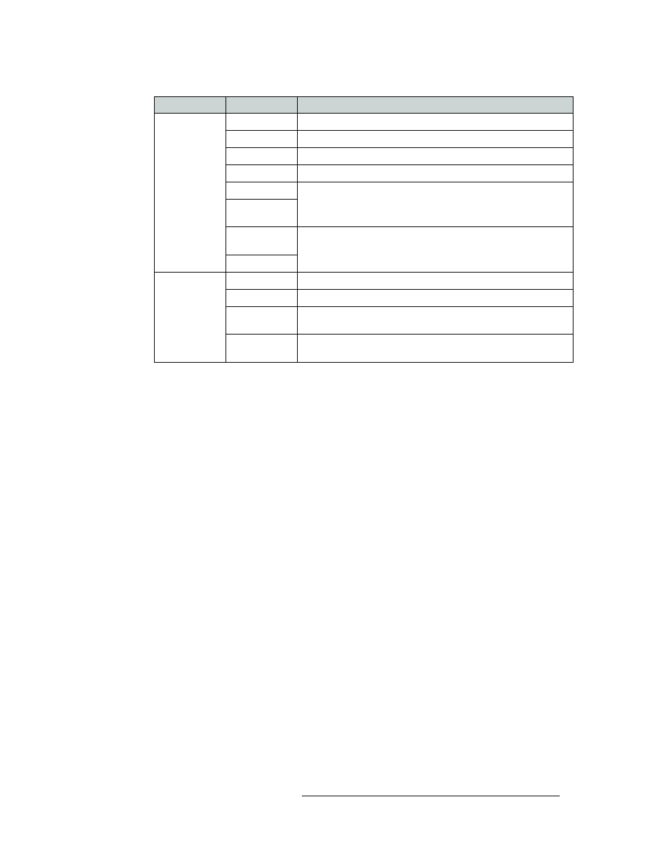
Levels
Level
Number assigned to the level. This number maps to the level name.
Router
Router to which the level is assigned.
Frame Type
Type (model number) of router.
Router IP
IP address assigned to the router.
Physical Inputs
These fields show the physical start and endpoints of the level within
the router.
Physical
Outputs
Controller
Sources
I/O numbering in the system controller may not match the physical I/
Os in the router. Use these fields to map the router I/Os to the system
controller I/O numbering.
Controller Dest
All CR Frames
Name
Name assigned to the compact router.
Frame Type
Type (model number) of compact router.
Panel Type
Type (model number) of control panel associated with the compact
router.
Subnet Mask
Subnet mask currently assigned to the device. It is recommended that
the subnet mask not be changed unless you are a developer.
Tab
Column
Description