Analog video routers, Digital audio routers, Tutorials – Grass Valley NVISION Compact CQX User Manual
Page 98
86
Rev 2.0 • 29 Mar 10
12. Tutorials
Products
The CQX video routers have a “mode” switch in addition to the 16-position frame ID switch. Both
are 16-position rotary switches that turn with a small screwdriver. The “mode” switch configures
the video format of the router.
Analog Video Routers
The 1RU analog video routers have 16×16, 16×4, or 8×8 crosspoints. The 2RU analog video rout-
ers have either 32×32 or 32×4 crosspoints.
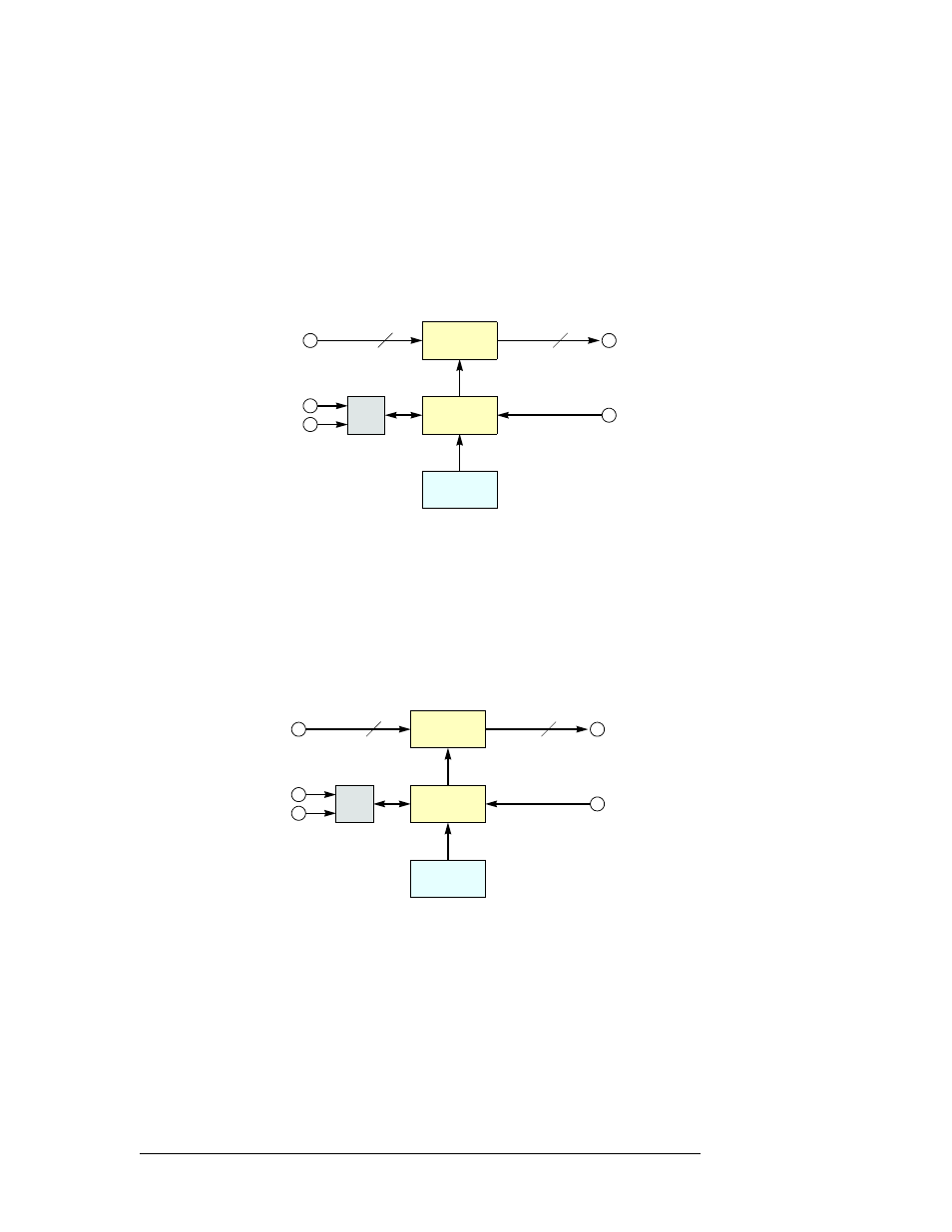
Figure 12-20 shows a simplified view of an analog video router:
Figure 12-20. Block Diagram of the Analog Video Router
The analog video routers switch NTSC (525i) or PAL (625i) video signals. The router outputs are
switched in sync with an external video reference if it is present.
Digital Audio Routers
The 1RU AES routers have 16×16, 16×4, or 8×8 crosspoints. The 2RU AES routers have either
32×32 or 32×4 (stereo) crosspoints.
Figure 12-21 is a simplified view of an AES router:
Figure 12-21. Block Diagram of the AES Router
If a video reference is present, the router is considered “synchronous” and regenerates output at
48kHz (nominally). The routers also perform a certain amount of signal processing if the input is
synchronous. If a video reference is not present, the router is asynchronous and passes input signals
straight through without any processing.
In synchronous mode, the router can perform mono routing, in which case, the maximum number
of signals is 2N, that is 8, 16, 32, or 64. In asynchronous mode, the router processes AES stereo
pairs.
M
N
µP
Logic
Inputs
Outputs
Crosspoint
Switch
Control
Panel
Video
Reference
Automation
Ethernet
(optional)
M = 8, 16 or 32
N = 4, 8, 16, or 32
M
N
µP
Logic
Inputs
Outputs
Crosspoint
Switch
Control
Panel
Video
Reference
Automation
Ethernet
(optional)
M = 8, 16 or 32
N = 4, 8, 16, or 32