HEIDENHAIN NC 124 User Manual
Page 115
14
Tables, Overviews and Diagrams
TNC 124
115
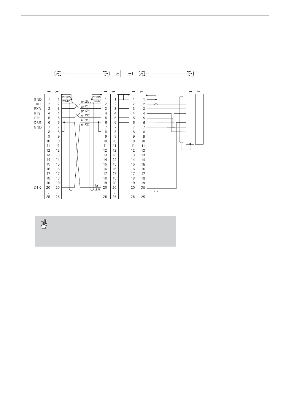
Pin layout and connecting cable for the data interface
Id.-Nr. 274 545 01
Id.-Nr. 286 998 ..
Id.-Nr. 239 758 01
TXD
RXD
DSR
GND
DTR
CTS
RTS
Transmit Data
Receive Data
Data Set Ready
Signal Ground
Data Terminal Ready
Clear To Send
Request To Send
1
2
3
4
5
6
7
8
9
1
2
3
4
5
6
7
8
9
ge
gn
rs
gr
br
rt
bl
YL
GN
PK
GY
BN
RD
BL
ws/br
WH/BN
The connector pin layout on the adapter block differs
from that on the TNC logic unit (X 21).
The X21 interface complies with safe separation
from line power as required by EN 50 178.
Connecting non-HEIDENHAIN devices
The connector pin layout on a non-HEIDENHAIN device may be quite
different from that on a HEIDENHAIN device. This depends on the unit
and the type of data transfer.
HEIDENHAIN devices
External
unit
e.g. FE
HEIDENHAIN
standard cable
3 m
HEIDENHAIN
connecting cable
max. 17 m
RS-232
adapter block
X21
TNC