Linear hole patterns – HEIDENHAIN NC 124 User Manual
Page 53
Advertising
4
Positioning with MDI
TNC 124
53
Linear hole patterns
Information required:
Coordinates of the first hole
Number of holes per row
Spacing between holes on a row
Angle between the first row and the angle reference axis
Number of rows
Spacing between rows
Bore hole or tap hole
The TNC calculates the coordinates of all holes.
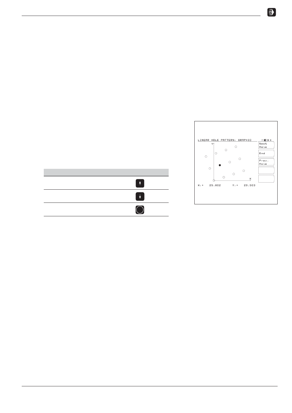
Linear hole pattern graphic
The graphic enables verification of the hole pattern before you start
machining. It is also useful when:
selecting holes directly
executing holes separately
skipping holes
Overview of functions
Function
Key
Go to the next-highest
input line
Go to the next-lowest
input line
Confirm entry values
ENT
Fig. 4.6:
TNC graphic for linear hole patterns
Advertising