Hole patterns in programs – HEIDENHAIN NC 124 User Manual
Page 85
7
Drilling, Milling Cycles and Hole Patterns in Programs
TNC 124
85
Hole patterns in programs
The information for the hole patterns Circle Pattern and
Linear Pattern
(see Chapter 4) can also be written to a pro-
gram.
Executing holes in hole patterns
The TNC either drills bore holes or tap holes at the hole positions in
the pattern. The bore hole or tap hole data, such as setup clear-
ance and hole depth, must be programmed in a cycle.
The TNC then executes the holes according to the selected cycle
that is programmed before the hole pattern cycle.
Hole pattern graphics
The hole patterns in a program can be displayed graphically.
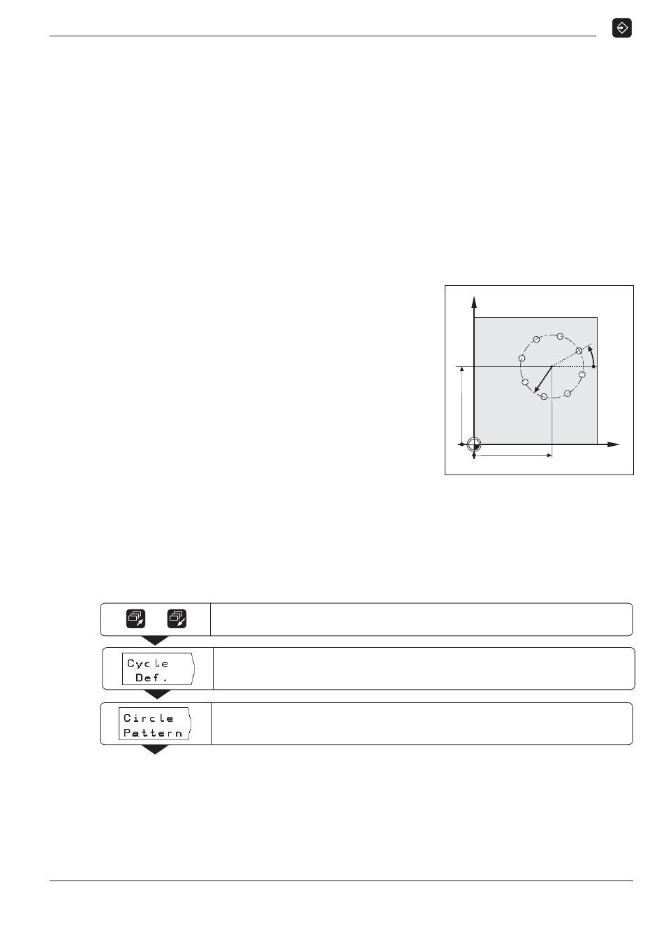
Programming example: Cycle 5.0 Circle Pattern (full circle)
Number of holes NO. :
8
Center point coordinates:
CCX
= 50 mm
CCY
= 50 mm
Bolt circle radius RAD:
20 mm
Starting angle between
X axis and first hole START:
30°
Hole data
A description of Cycle 1.0 Pecking
starts on page 79.
Clearance height HEIGHT:
+ 50 mm
Setup clearance DIST:
2 mm
Coordinate of the
workpiece surface SURF:
0 mm
Hole depth DEPTH:
15 mm
Pecking depth PECKG:
5 mm
Dwell time DWELL:
0.5 s
Feed rate F:
80 mm/min
Example: Entering bolt hole circle data into a program
Operating mode: PROGRAMMING AND EDITING
Y
X
30°
R20
50
50
0
0
Page to the third soft-key row.
/
Select Cycle Definition.
Select Circle Pattern.
The soft-key row switches to a deeper level.