X +z +y, Machine axis movements and position feedback – HEIDENHAIN NC 124 User Manual
Page 14
1
Fundamentals of Positioning
14
TNC 124
Y
X
Z
+X
+Z
+Y
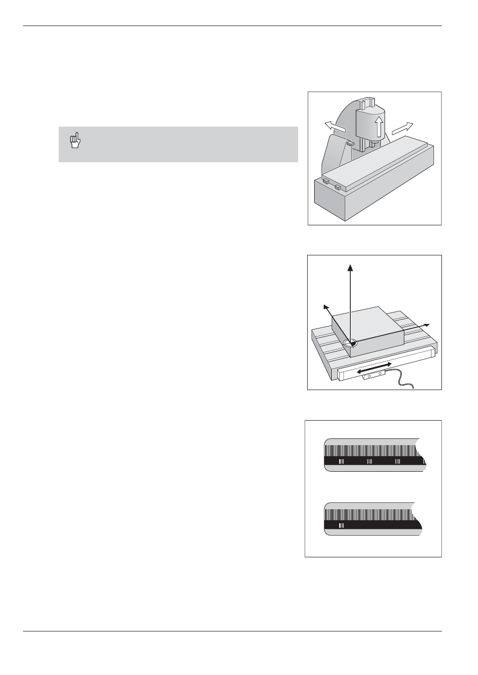
Fig. 1.8:
On this machine the tool moves in
the Y and Z axes; the workpiece
moves in the X axis.
Fig. 1.9:
Linear position encoder, here for
the X axis
Fig. 1.10: Linear scales: above with distance-
coded reference marks, below with
one reference mark
Machine axis movements and position feedback
Programming tool movements
During workpiece machining, an axis position is changed either by
moving the tool or by moving the machine table on which the
workpiece is fixed.
When entering tool movements in a part program you
always program as if the tool is moving and the work-
piece is stationary.
Position feedback
The position feedback encoders linear encoders for linear axes,
angle encoders for rotary axes convert the movement of the ma-
chine axes into electrical signals. The control evaluates these sig-
nals and constantly calculates the actual position of the machine
axes.
If there is an interruption in power, the calculated position will no
longer correspond to the actual position. When power is restored,
the TNC can re-establish this relationship.
Reference marks
The scales of the position encoders contain one or more reference
marks. When a reference mark is passed over, it generates a signal
which identifies that position as the reference point (scale reference
point = machine reference point). With the aid of this reference mark
the TNC can re-establish the assignment of displayed values to ma-
chine axis positions.
If the position encoders feature distance-coded reference marks,
each axis need only move a maximum of 20 mm (0.8 in.) for linear
encoders, and 20° for angle encoders.