Important notes, Important notes -14, Finish the ethernet/ip option card installation – Yaskawa CM092 User Manual
Page 19
Installation 1-14
Finish the EtherNet/IP Option Card Installation
1.
Remove power from the AC drive and wait for the charge lamp to be completely extinguished. Wait at least five additional minutes for
the drive to be completely discharged. Measure the AC drive DC bus voltage and verify that it is at a safe level.
2.
Reinstall all drive covers and the operator keypad. Apply power to the drive.
3.
Set parameters b1-01 and b1-02 to their appropriate values.
4.
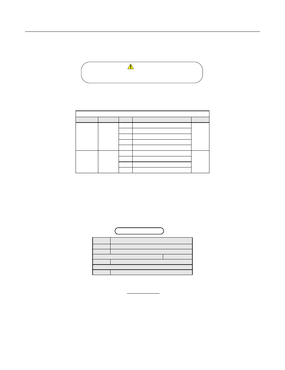
Refer to the table below for available b1-01 and b1-02 values.
Important Notes
1.
It is strongly recommended that shielded CAT-5 cable be used for all network cables.
2.
Switches implementing IGMP snooping are strongly recommended. When IGMP snooping is used, devices will only receive the multi-
cast packets in which they are interested.
3.
The maximum number of simultaneous connections is: 1 for I/O, 4 for Explicit, 2 for DriveWizard.
4.
Place the supplied MAC ID label on the side of the drive either above or below the drive nameplate.
Fig 1.7 – Placing the MAC ID Label
5.
To simplify the drive configuration, obtain EDS files at www.yaskawa.com. From the Yaskawa web site, select Downloads => By
Inverter Drives => By Product => Network Comms-Ethernet. Then select the appropriate EDS file based on drive series and the lat-
est version of those listed. EDS files for individual drive models are compressed into a single Zip file. Unzip these files into a temporary
directory for installation. For example: The current file containing the G7U EDS files is named EDS_G7U_UTC000068_V1_01.zip.
To extract the EDS file for model 20P4, extract the EDS file named G7U20P4_UTC000068_V1_0*.eds.
Refer to the appropriate user, programming or parameter access manual for a complete list of drive parameters and registers available. A list
of applicable manuals is available at the beginning of this document.
Table 1.4 – Run and Reference Source Selection
Parameter
Function
Data
Description
Default
b1-01
Reference
Source
0
Digital Operator
1
1
Terminal Strip
2
Built-in Modbus RTU RS-485 Terminals
3
Option Kit (EtherNet/IP Option)
4
Pulse Input (F7 and G7 Only)
b1-02
Run
Source
0
Digital Operator
1
1
Terminal Strip
2
Built-in Modbus RTU RS-485 Terminals
3
Option Kit (EtherNet/IP Option)
MODEL:
CIMR-G7U20P4
SPEC: 20P41A
INPUT:
AC3PH 200 - 240V 50/60Hz 3.8A
OUTPUT:
AC3PH 0 - 240V 0 – 400Hz 3.2A 1.2kVA
O/N:
MASS:
3.0kg
S/N:
1W0149999991W0001
PRG:
1W0149999991W0001
FILE NO:
E131457
MAC ID: 00-20-B5-24-11-13
Dangerous voltages in excess of 400VDC (230V drives) or 800VDC
(460V drives) are present at the DC bus terminals of the drive.
WARNING!