Drive diagnostics web page – Yaskawa CM092 User Manual
Page 29
Browser Interface 2-6
Drive Diagnostics Web Page
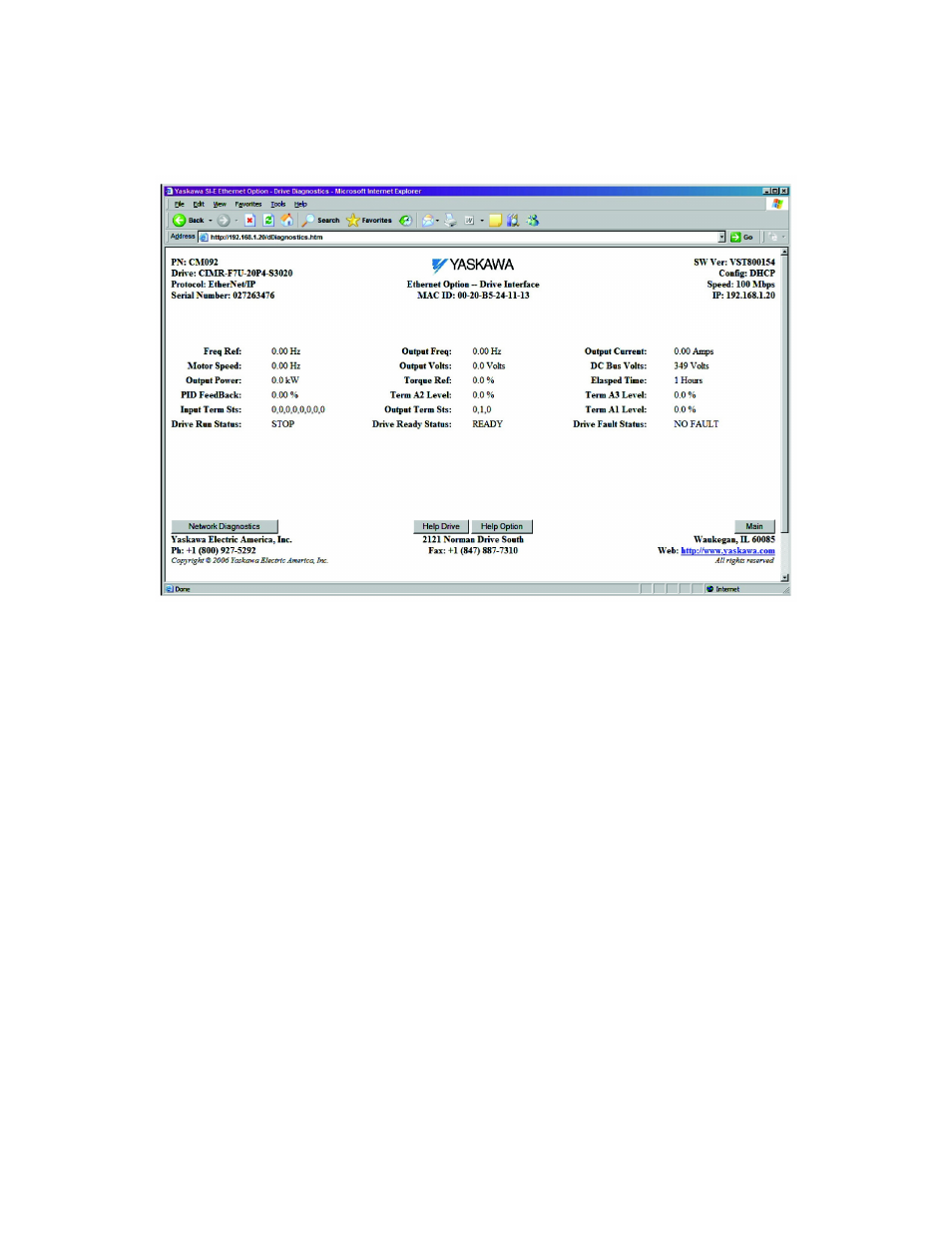
The drive diagnostics page contains the standard header and footer along with diagnostic information specific to the current drive.
Fig 2.5 – Drive Diagnostics Web Page
Freq Ref:
Frequency Reference – Monitor Parameter U1-01.
Motor Speed:
Motor Speed – Monitor Parameter U1-05.
Output Power:
Output Power – Monitor Parameter U1-08.
PID Feedback:
PID Feedback in %.
Input Terminal Sts:
The Digital Input status as bit field – Monitor Parameter U1-10.
Drive Run Status:
Indicates RUN/STOP state of the drive.
Output Freq:
Output Frequency – Monitor Parameter U1-02.
Output Volts:
Output Voltage – Monitor Parameter U1-06.
Torque Ref:
Torque Reference - Monitor Parameter U1-09.
Term A2 Level:
The analog input A1 Terminal A2 (14) monitor value U1-16.
Output Terminal Sts:
Digital Output status as bit field – Monitor Parameter U1-11.
Drive Ready Status:
Indicates the drive READY status.
Output Current:
Output Current – Monitor Parameter U1-03.
DC Bus Volts:
DC bus Voltage – Monitor Parameter U1-07.
Elapsed Time:
Elapsed Time – Monitor Parameter U1-13.
Term A3 Level:
The analog input Terminal A3 (16) monitor value U1-17.
Term A1 Level:
The analog input Terminal A1 monitor value U1-15.
Drive Fault Status:
Indicates drive FAULT status.