Understanding the test steps, Understanding the test steps -2 – Altera Avalon Verification IP Suite User Manual
Page 205
• The test program controls the BFMs using the BFM API to drive and monitor transactions.
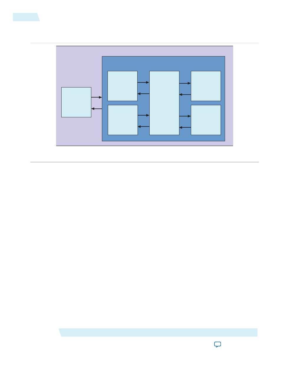
Figure 16-1: Top-Level Testbench for Avalon-ST DUT Component
Qsys Generated Testbench
Top-Level File
Test
Program
Avalon-ST
Single-Clock
FIFO Buffer
(DUT)
Avalon Clock
Source BFM
Avalon-ST
Source BFM
Avalon-ST
Sink BFM
Avalon Reset
Source BFM
Understanding the Test Steps
The test flow includes the following steps:
1. The test program initializes the BFMs.
2. The test program runs the following three parallel processes:
a. Process 1 creates and sends four test transactions to the source BFM. The transactions consist of the
following six Avalon-ST signals:
data
,
channel
,
error
,
empty
,
startofpacket
,
endofpacket
, and
idle
. The Avalon-ST Source BFM drives the transactions to the Avalon-ST Single-Clock FIFO buffer.
In addition, the Avalon-ST Source BFM keeps a local copy of the transactions for future reference.
The Avalon-ST Source BFM prints the transaction values in the ModelSim transcript console.
b. Process 2 controls the Avalon-ST Sink BFM. When the Avalon-ST Sink BFM receives a transaction,
it completes the following steps:
• It reads the transaction values.
• It prints the transaction values on the ModelSim transcript console.
• It compares the values it receives to the values from the Avalon-ST Source BFM.
• It reports any mismatch in values as failures.
• During this process, the Avalon-ST Sink BFM backpressures the Avalon-ST Single-Clock FIFO
buffer.
c. Process 3 measures the response latency when the Avalon-ST Single-Clock FIFO buffer backpressures
the Avalon-ST Source BFM. The Avalon-ST Source BFM prints the transaction values on the ModelSim
transcript console.
Avalon-ST Verilog HDL Testbench
Altera Corporation
Understanding the Test Steps
16-2