Understanding the simulation results, Understanding the simulation results -35 – Altera Integer Arithmetic IP User Manual
Page 136
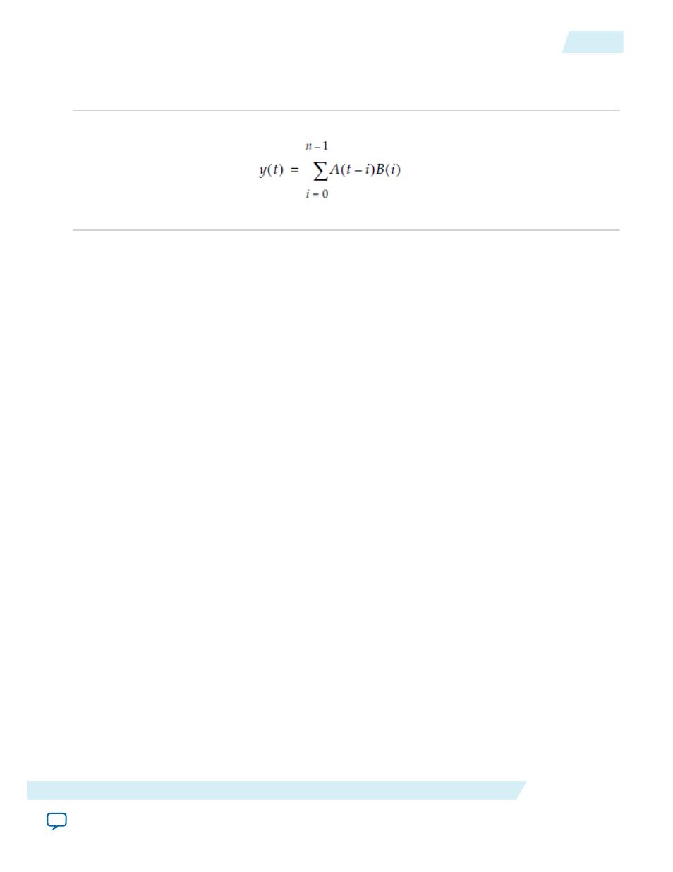
This design example uses the ALTMULT_ADD megafunction to implement a simple FIR filter as shown
in the following equation. This example uses the MegaWizard Plug-In Manager in the Quartus II
software.
n represents the number of taps, A(t) represents the sequence of input samples, and B(i) represents the
filter coefficients.
The number of taps (n) can be any value, but this example is of a simple FIR filter with n = 4, which is
called a 4-tap filter. To implement this filter, the coefficients of data B is loaded into the B registers in
parallel and a
shiftin
register moves data A(0) to A(1) to A(2), and so on. With a 4-tap filter, at a given
time (t), the sum of four products is computed. This function is implemented using the shift register chain
option in the ALTMULT_ADD megafunction.
With reference to the equation, input B represents the coefficients and data A represents the data that is
shifted into. The A input (data) is shifted in with the main clock, named
clock0
. The B input
(coefficients) is loaded at the rising edge of
clock1
with the enable signal held high.
:
fir_fourtap.qar (archived Quartus II design files)
altmult_add_ex_msim (ModelSim-Altera files)
Understanding the Simulation Results
The following settings are observed in this example:
• The widths of the data inputs are all set to 16 bits
• The width of the output port,
result[]
, is set to 34 bits
• The input registers are all operating on the same clock
The following figure shows the expected simulation results in the ModelSim-Altera software.
UG-01063
2014.12.19
Understanding the Simulation Results
9-35
ALTMULT_ADD (Multiply-Adder)
Altera Corporation