Understanding the simulation results, Understanding the simulation results -5 – Altera Integer Arithmetic IP User Manual
Page 155
This design example uses the LPM_MULT and PARALLEL_ADD megafunctions to generate a shift
accumulator. This function implements the shift-and-accumulate operation after the multiplication
process in a design block, such as a serial FIR filter. This example uses the MegaWizard Plug-In Manager
in the Quartus II software.
• shift_accum.qar (archived Quartus II design files)
• parallel_adder_ex_msim (ModelSim-Altera files)
Understanding the Simulation Results
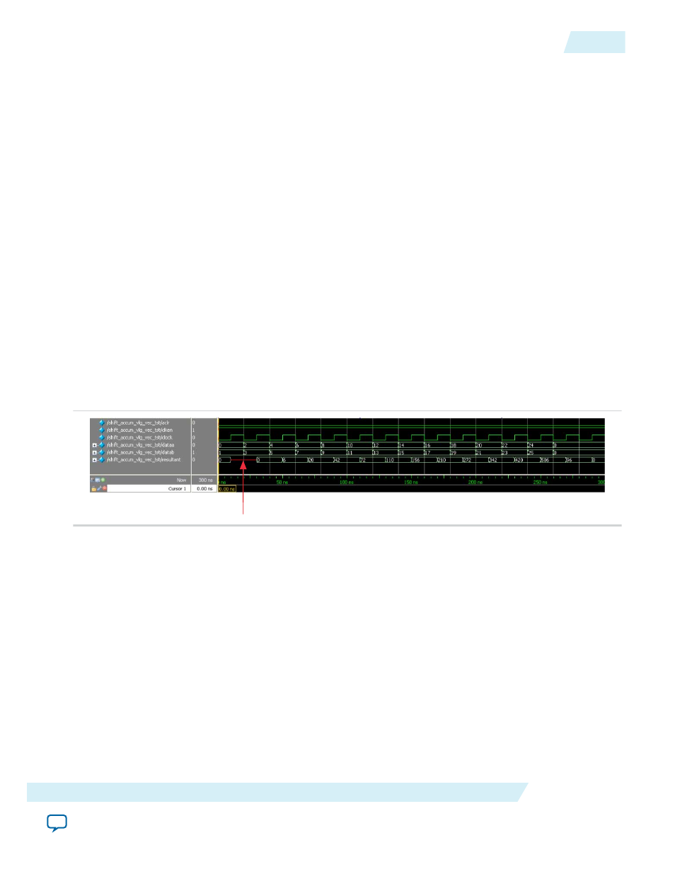
The following settings are observed in this example:
The widths of the input ports,
dataa[]
and
datab[]
, are set to 9 bits
The width of the output port,
resultant[]
, is set to 10 bits
The asynchronous clear (
aclr
) and clock enable (
clocken
) input ports are enabled
The latency is set to one clock cycle for the multiplier and one clock cycle for the parallel adder, resulting
in a total output latency of two clock cycles. Hence, the result is seen on the
resultant[]
port two clock
cycles after the input data is available.
The following figure shows the expected simulation results in the ModelSim-Altera software.
Figure 12-2: PARALLEL_ADDER Simulation Results
Note: At start up, an undefined value is seen on the
resultant[]
port, but this value is merely due to the
behavior of the system during start-up and hence, can be ignored
UG-01063
2014.12.19
Understanding the Simulation Results
12-5
PARALLEL_ADD (Parallel Adder)
Altera Corporation