F. static and dynamic phase alignment, Static alignment, Fer to – Altera POS-PHY Level 4 IP Core User Manual
Page 125: Appendix f, static, And dynamic phase alignment
December 2014
Altera Corporation
POS-PHY Level 4 IP Core User Guide
F. Static and Dynamic Phase Alignment
The SPI-4.2 standard specifies two mechanisms for receiving data from the physical
layer: static and dynamic alignment. Both follow the same electrical specifications, but
differ in their timing requirements.
Static Alignment
Static alignment is more traditional as it calls for a specific setup and hold time at the
receiver. The implementation in the SPI-4.2 specification is complicated by the double
data rate (DDR) clock. The actual sampling edge is implied by a synthesized clock
related to the input reference. In the specification, the receiver timing is bound by a
maximum differential between the clock and data, or frame signals. The receiver
sampling window has a fixed relationship to the input clock reference.
The timing margin for a statically-aligned system is calculated by subtracting all of
the delays from the overall period of the clock. These delays include:
■
Transmitter clock-to-data skews
■
Receiver sampling windows
■
Jitter components
The remaining time is allocated to the connection between parts. All of the differential
delays between traces—caused by factors such as board routing, transmission line
effects, and connector skews—consume this margin of time. Static alignment is
appropriate for areas where such factors can be well controlled. For example, the
connection between adjacent devices is generally short, and can be controlled—at
layout time—to within a few millimetres.
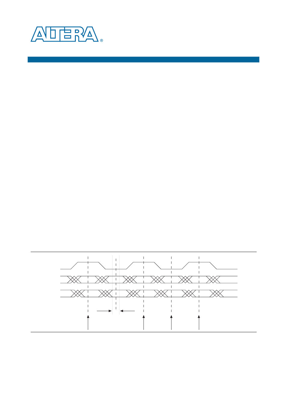
Figure F–1
shows an example of static alignment.
Figure F–1. Static Alignment Timing Diagram
Clock
Data 1
Data 2
Receiver Sampling
Window
Inferred
Sample Clock