Altera POS-PHY Level 4 IP Core User Manual
Page 46
4–8
Chapter 4: Functional Description—Receiver
Block Description
POS-PHY Level 4 IP Core User Guide
December 2014
Altera Corporation
The port number is provided with a request signal to both the status calculator and
status hold blocks, but only the output of one block, according to the value of the
ctl_ry_fifostatoverride
input, is sent to the status FSM block to be inserted into the
outgoing status frame. In the individual buffers mode, the ctl_ry_fifostatoverride
input is forced low to always select the calculated value. In the shared buffer with
embedded addressing mode, the ctl_ry_fifostatoverride input is set according to
the option selected in IP Toolbench for the status source parameter. If the user-
controlled option is selected, you must write buffer status per-port into the status hold
block via the external status interface. Otherwise, the interface is ignored and the
calculated value is used. This external control interface features an 8-bit address bus, a
2-bit status port value, and a valid signal (refer to
).
1
Due to the round trip latency of the status channel, especially at high calendar
lengths, the hysteresis between the AE and AF values (in addition to the possibility of
the override capabilities listed above) may be such that a transition from starving to
satisfied (and vice versa) can occur. In the event that a transmitting device does not
allow these types of transitions (require hungry state to be observed between starving
and satisfied), you should ensure that the difference between AE and AF values is
greater than the hysteresis between the thresholds.
The external status address you provide does not have to be incrementing or have any
set sequence. You can provide any address value, at any time. If the external address
provided is for an unprovisioned port, the value is written into the internal RAM at
that address, but the internal status block never reads from that location.
The status hold block reads the contents of the memory where you have stored the
status of the external FIFO buffer(s).
The status calculator block compares the Atlantic FIFO buffer fill levels to the AE and
AF values for the requested port. In the shared buffer with embedded addressing
mode, because there is a single Atlantic FIFO buffer, the status for any port is
calculated according to the single level as opposed to a per-port basis.
The outgoing status of all ports is forced to satisfied ,if the datapath clock-crossing
buffer or Atlantic buffer overflows.
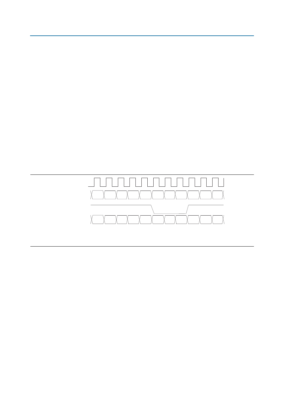
Figure 4–3. Receiver External Status Timing Diagram
Notes to
(1) The external status address does not have to be incrementing. Any value within calendar length can be provided at any time.
(2) The calendar status after the last clock cycle shown has: port 0 = 2’b00, port 1 = 2’b10, port 2 = 2’b01, and port 3 = 2’b00.
rxsys_clk
ctl_ry_extstat
ctl_ry_extstat_val
ctl_ry_extstat_adr
2'b00
2'b00
2'b00
2'b00
2'b01
2'bxx
2'bxx
2'bxx
2'b01
2'b00
2'b10
8'd0
8'd0
8'd0
8'd1
8'd1
8'd0
8'd0
8'd0
8'd2
8'd3
8'd1