Reset structure, Error flagging and handling, Fer to – Altera POS-PHY Level 4 IP Core User Manual
Page 50: Error flagging and
4–12
Chapter 4: Functional Description—Receiver
Reset Structure
POS-PHY Level 4 IP Core User Guide
December 2014
Altera Corporation
Reset Structure
By default, the rxreset_n signal is the asynchronous global reset for the IP core. It is
internally metastable hardened and passed to each of the individual clock domains.
Asserting reset deletes all data in the buffers, and resets all state bits.
In addition to the reset, asynchronous reset and locked signals are provided for the
internal PLL, if present. The PLL should be reset and stable along with all other clocks
before the reset is released.
Error Flagging and Handling
This section describes how the POS-PHY Level 4 receiver IP core responds to various
errors.
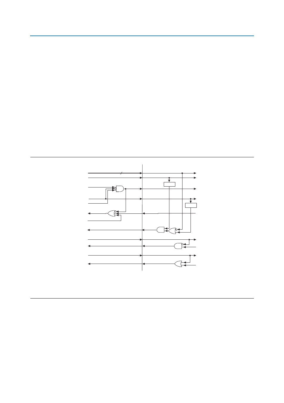
Figure 4–6
shows an example user configuration for the POS-PHY Level 4 receiver IP
core.
Figure 4–6. Example User Receiver Configuration
Note to
Figure 4–6
:
(1) The ctl_rd_dpa_force_unlock signal is not asserted until after start up.
(2) The delay is to ensure the ctl_rd_dpa_force_unlock signal is asserted for at least one clock cycle.
(3) The counter is intended to pulse the ctl_rd_dpa_force_unlock signal after the frame has been out of synchronization for some time.
17
LVDS Locked
ctl_ry_rsfrm
ctl_rd_dpa_
force_
unlock
aN_arxreset_n
err_rd_abuf_oflw
ctl_rd_abuf_flush
stat_rd_dpa_lvds_locked
stat_rd_dpa_locked
stat_rd_rdat_sync
stat_rd_rx_dip4_oos
User Force Frame
err_ry_fifo_oflwN
User Atlantic Reset
err_rd_abuf_oflw
User Buffer Flush
DPA Locked
Receiver Trained
DIP-4 OOS
Atlantic Buffer Ready
Send Framing
RSFRM Control Bit from
Avalon Control Register
DPA Force Unlock
Atlantic Buffer Overview
Atlantic Buffer Reset
Alignment
Buffer Overflow
Alignment Buffer Flush
Counter
Internal SPI-4.2 Receiver Core
Example User Side Connections
Delay