Receiver options – Altera POS-PHY Level 4 IP Core User Manual
Page 36
3–16
Chapter 3: Parameter Settings
Protocol Parameters
POS-PHY Level 4 IP Core User Guide
December 2014
Altera Corporation
Receiver Options
The Almost empty (AE) and Almost full (AF) thresholds segregate the receiver FIFO
buffer into three states, depending on the fill levels: starving, hungry, and satisfied.
The SPI-4 Phase 2 specification defines two-bit status values for starving, hungry, and
satisfied. These two-bit values are based on the available space in the FIFO buffer and
on the AE and AF parameter settings:
■
Starving—when the number of elements in the FIFO buffer is less than, or equal to,
the AE threshold
■
Hungry—when the number of elements in the FIFO buffer is between the AE
threshold and the AF threshold
■
Satisfied—when the number of elements in the FIFO buffer is greater than the AF
threshold
The starving, hungry, and satisfied conditions are reported to the adjacent transmitter
on the rstat bus, which operates at up to ¼ of the rdclk frequency.
These thresholds are defined in terms of bytes, with a valid range from zero to buffer
size
.
1
AE must be lower than or equal to AF.
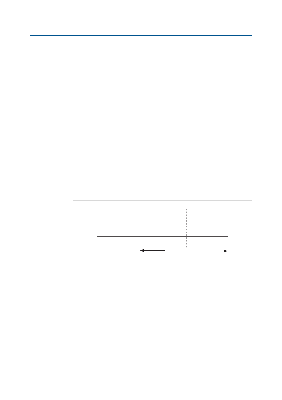
Figure 3–5
illustrates the relationship between the AE and AF thresholds and the
MaxBurst1
and MaxBurst2 values.
The FIFO buffer threshold low (FTL) value for receiver variations controls when the
aN_arxdav
signal is asserted for the read side of the FIFO buffer. If the fill level of the
buffer is higher than the FTL value, the aN_arxdav signal is asserted indicating that
there is a burst of data available.
1
There is no requirement to wait for the aN_arxdav signal to be asserted, you can read
from the buffer at any time.
Figure 3–5. FIFO Buffer Thresholds
Notes to
Figure 3–5
:
(1) L
MAX
corresponds to the worst-case response time from sending a status update over the FIFO status channel until
observing the reaction to that update on the corresponding data path.
(2)
corresponds to the difference between the granted credit and the actual data transfer length. This difference arises
from various protocol overheads.
(3) The MaxBurst1 and MaxBurst2 values are defined by the adjacent device’s transmitter. Determining the optimal
MaxBurst1 and MaxBurst2 values is application-specific, and requires an analysis of the data flows, beyond the
scope of this user guide.
AE
AF
Starving
Hungry
Satisfied
Lmax +
ε
Lmax + MaxBurst1+
ε
Lmax + MaxBurst2+
ε
(Empty)
(Full)