Metering – Basler Electric DGC-2020HD Modbus Protocol User Manual
Page 130
124
9469300991 Rev A
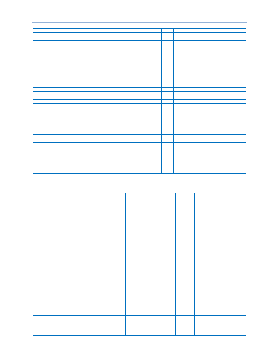
Default Register Table
DGC-2020HD Modbus
™ Protocol
Name
Description
Group Register Type Bytes R/W
Unit
Range
Analog Input 3 Protection
Threshold 4 Pickup
GG
8752
Float
4
R W n/a
-999999 - 999999
Analog Input 3 Protection
Threshold 4 Activation Delay GG
8754
Float
4
R W Second 0 - 300
Analog Input 3 Protection
Threshold 4 Alarm
Configuration
GG
8756
Uint32 4
R W n/a
Status Only=0
Pre-Alarm=1
Alarm=2
Analog Input 4 Protection
Parameter Minimum
GG
8758
Float
4
R W n/a
-999999 - 999999
Analog Input 4 Protection
Parameter Maximum
GG
8760
Float
4
R W n/a
-999999 - 999999
Analog Input 4 Protection
Current Minimum
GG
8762
Float
4
R W Milliamp 4 - 20
Analog Input 4 Protection
Current Maximum
GG
8764
Float
4
R W Milliamp 4 - 20
Analog Input 4 Protection
Voltage Minimum
GG
8766
Float
4
R W Volt
0 - 10
Analog Input 4 Protection
Voltage Maximum
GG
8768
Float
4
R W Volt
0 - 10
Analog Input 4 Protection
alarm config
GG
8770
Uint32 4
R W n/a
Status Only=0
Pre-Alarm=1
Alarm=2
Analog Input 4 Protection
Hysteresis
GG
8772
Float
4
R W Percent 0 - 100
Analog Input 4 Protection
Arming Delay
GG
8774
Float
4
R W Second 0 - 300
Analog Input 4 Protection
Threshold 1 Pickup
GG
8776
Float
4
R W n/a
-999999 - 999999
Analog Input 4 Protection
Threshold 1 Activation Delay GG
8778
Float
4
R W Second 0 - 300
Analog Input 4 Protection
Threshold 1 Alarm
Configuration
GG
8780
Uint32 4
R W n/a
Status Only=0
Pre-Alarm=1
Alarm=2
Analog Input 4 Protection
Threshold 2 Pickup
GG
8782
Float
4
R W n/a
-999999 - 999999
Analog Input 4 Protection
Threshold 2 Activation Delay GG
8784
Float
4
R W Second 0 - 300
Analog Input 4 Protection
Threshold 2 Alarm
Configuration
GG
8786
Uint32 4
R W n/a
Status Only=0
Pre-Alarm=1
Alarm=2
Analog Input 4 Protection
Threshold 3 Pickup
GG
8788
Float
4
R W n/a
-999999 - 999999
Analog Input 4 Protection
Threshold 3 Activation Delay GG
8790
Float
4
R W Second 0 - 300
Analog Input 4 Protection
Threshold 3 Alarm
Configuration
GG
8792
Uint32 4
R W n/a
Status Only=0
Pre-Alarm=1
Alarm=2
Analog Input 4 Protection
Threshold 4 Pickup
GG
8794
Float
4
R W n/a
-999999 - 999999
Analog Input 4 Protection
Threshold 4 Activation Delay GG
8796
Float
4
R W Second 0 - 300
Analog Input 4 Protection
Threshold 4 Alarm
Configuration
GG
8798
Uint32 4
R W n/a
Status Only=0
Pre-Alarm=1
Alarm=2
Metering
Name
Description
Group Register Type Bytes R/W
Unit
Range
ECU Metering
ECU Lamp Status Data
GG
10000
Uint32 4
R
n/a
Bit 0 = Protect
Bit 1 = Not Used
Bit 2 = Not Used
Bit 3 = Warning
Bit 4 = Stop
Bit 5 = Not Used
Bit 6 = Not Used
Bit 7 = Malfunction
Bit 8 = Not Used
Bit 9 = Not Used
Bit 10 = Not Used
Bit 11 = Not Used
Bit 12 = Not Used
Bit 13 = Not Used
Bit 14 = Not Used
Bit 15 = Not Used
Bit 16 = Not Used
Bit 17 = Not Used
Bit 18 = Not Used
Bit 19 = Not Used
Bit 20 = Not Used
Bit 21 = Not Used
Bit 22 = Not Used
Bit 23 = Not Used
Bit 24 = Not Used
Bit 25 = Not Used
Bit 26 = Not Used
Bit 27 = Not Used
Bit 28 = Not Used
Bit 29 = Not Used
Bit 30 = Not Used
Bit 31 = Not Used
ECU Metering
DTC Count Data
GG
10002
Uint32 4
R
n/a
Active stored in upper byte,
Previous stored in lower byte
ECU Metering
CAN Coolant Level
GG
10004
Uint32 4
R
n/a
Percent
Reserved
10006-7
Gen Voltage Meter Mag 1 VA
GG
10008
Float
4
R
Volt
0 - 2000000000