5 hydraulic valves connection, Hydraulic valves connection, Installation – ARAG Bravo 400S Crop sprayer User Manual
Page 11
11
INSTALLATION
6.5
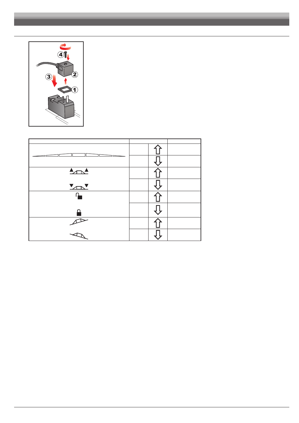
Hydraulic valves connection
Fig. 13
Bravo 400S can control up to 9 hydraulic functions through double-acting valves.
Fix the connectors to the relevant valves according to the initials indicated in your assembly general diagram (par. 5.1).
• Position seal (
1
) onto connector (
2
), then connect the latter pressing it fully home (
3
):
during this operation, take special care not to bend valve electric contacts.
• Insert screw inside connector, and screw it (
4
) until it is tightened.
The function of each switch on the hydraulic function control panel is described below.
• Connect the connector marked with "DD" to the pilot valve, and then the other connectors, as specified on the table:
CONTROL
MOVEMENT
CONNECTOR
Section movement
1 - 2 - 3 - 4 - 5 - 6
Opening
1 ÷ 6 A
Closing
1 ÷ 6 C
Boom height
Opening
AA
Closing
AC
Boom locking
Opening
BA
Closing
BC
Boom leveling
Opening
CA
Closing
CC