5 position on farming machine, 1 system recommended composition, System recommended composition – ARAG Bravo 400S Crop sprayer User Manual
Page 6: Installation
Advertising
6
5
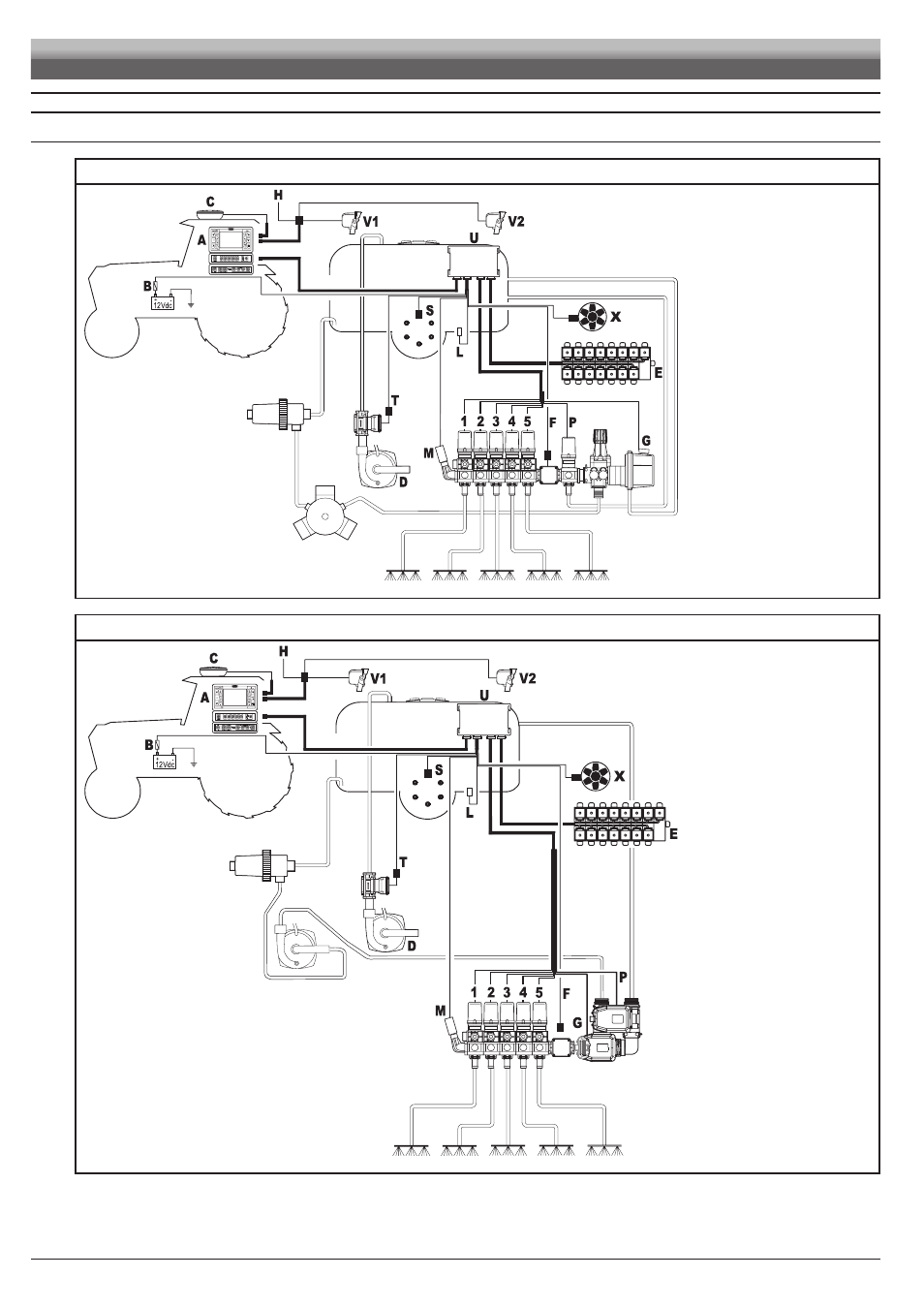
POSITION ON FARMING MACHINE
5.1
System recommended composition
ASSEMBLY DIAGRAM FOR CROP SPRAYER WITH DIAPHRAGM PUMP
Fig. 2
Legend:
A Monitor
B Battery
C
GPS receiver
D
Filling pump
E
Oil-hydraulic unit
F Flowmeter
G
Main valve
H
External main control
L
Level sensor
M Pressure sensor
P
Control valve
S
Speed sensor
T
Filling flowmeter
U
Remote Control Unit (RCU)
V1 Camera 1
V2 Camera 2
X
RPM sensor
1-13 Section valves
ASSEMBLY DIAGRAM FOR CROP SPRAYER WITH CENTRIFUGAL PUMP
Fig. 3
Legend:
A Monitor
B Battery
C
GPS receiver
D
Filling pump
E
Oil-hydraulic unit
F Flowmeter
G
Main valve
H
External main control
L
Level sensor
M Pressure sensor
P
Control valve
S
Speed sensor
T
Filling flowmeter
U
Remote Control Unit
V1 Camera 1
V2 Camera 2
X
RPM sensor
1-13 Section valves
INSTALLATION
Advertising