Implement upper view, 13 implement geometry settings, System with rear / front 3-point hitch) – ARAG Bravo 400S Crop sprayer User Manual
Page 42: Advanced setup "implement
42
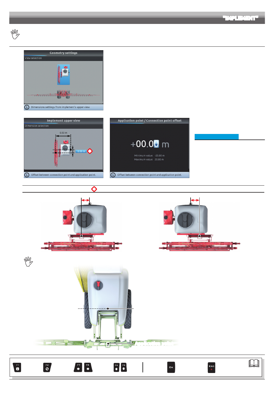
The geometry of the displayed implement depends on the selected basic settings (ch. 9).
10.1.13 Implement geometry settings (SYSTEM WITH REAR / FRONT 3-POINT HITCH)
Fig. 142
Enter farming machine measures:
- Press the arrow keys (UP, DOWN, LEFT, RIGHT) to move across different implement views.
- Confirm by pressing
OK
to enter setup.
*
Fig. 143
Fig. 144
• Implement upper view
- Press the arrow keys (UP, DOWN, LEFT, RIGHT)
to move across values: the description of the
selected value will appear on the display.
- Confirm by pressing
OK
to enter setup.
- Enter the value.
- Select and enter, one by one, all values.
*
Offset between connection point and application point
Application point
Connection point
- 1.50 m
NEGATIVE VALUES
The application point is
to the left of the
connection point.
Fig. 145
Application point
Connection point
+ 1.50 m
POSITIVE VALUES
The application point is to the
right of the connection point.
Fig. 146
THE CONNECTION POINT OF A SELF-PROPELLED MACHINE COINCIDES WITH THE REAR AXLE OF THE VEHICLE.
Connection point
Application point
Fig. 147
CONTINUES > > >
ADVANCED SETUP
"IMPLEMENT"
Par.
Exits the function
or data change
Confirm access
or data change
Scroll
(LEFT /
RIGHT)
Delete
selected
character
Increase /
Decrease
of data
Scroll
(UP /
DOWN)
Enter
selected
character