9 basic settings, Ch. 9, Basic settings – ARAG Bravo 400S Crop sprayer User Manual
Page 18: Setup "basic settings, Basic implement settings
18
SETUP
"BASIC SETTINGS"
9
BASIC SETTINGS
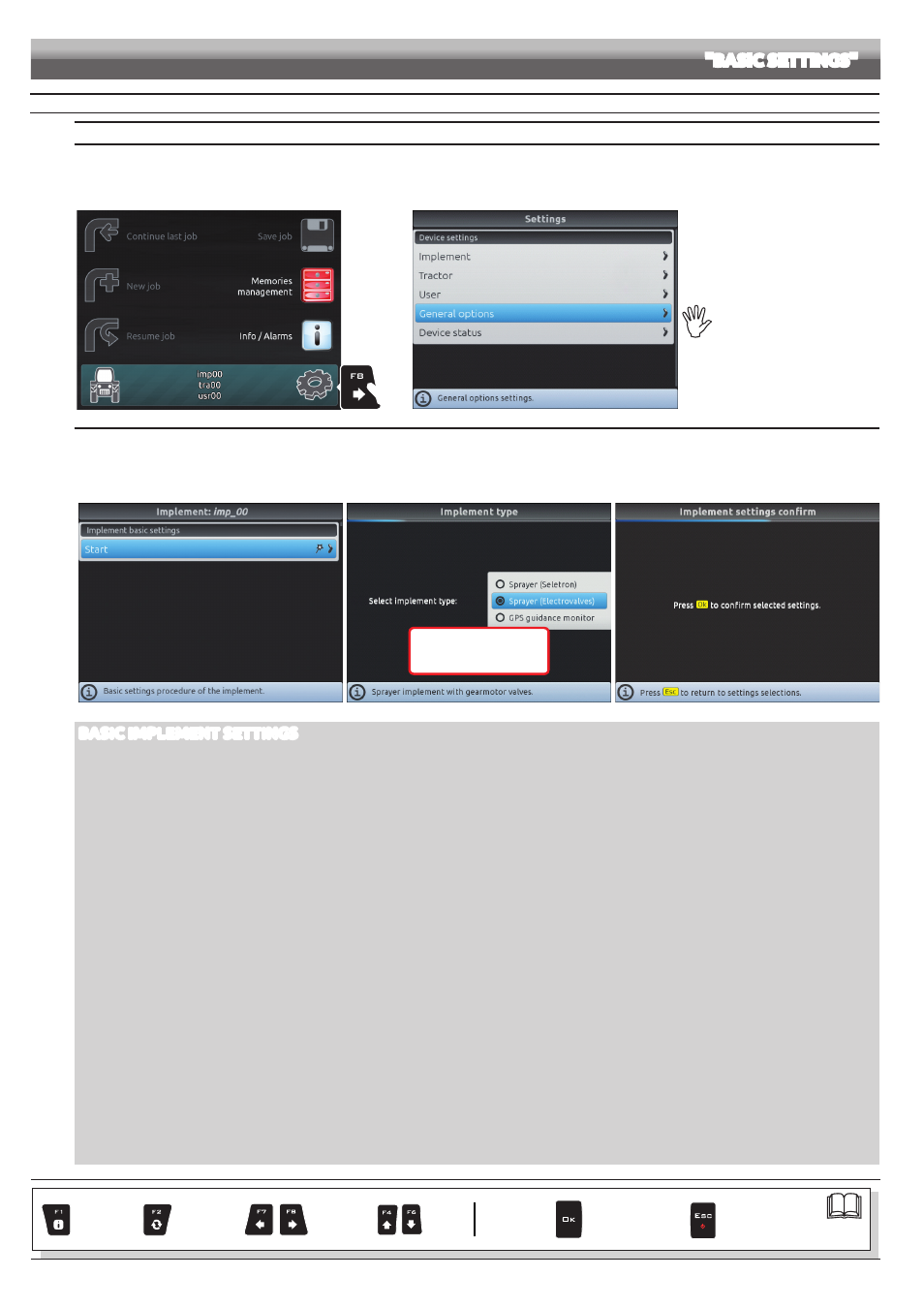
GUIDED SETUP PROCEDURE UPON FIRST SWITCHING ON
1 LANGUAGE SETTING
- In the "Home" screen (Fig. 33) press
F8
to enter the
Settings
menu (Fig. 34).
- Select
General options > Language
and set the language of Bravo 400S.
- Press
ESC
and return to the
Settings menu
. Now select
Implement
to start guided setup procedure as shown in Fig. 35.
1
Fig. 33
Fig. 34
For a correct use of the keys
during setting, refer to par. 7.4.
2 IMPLEMENT
- Upon first switching on, Bravo 400S starts the guided setup procedure for the
Implement
: go through each step selecting the desired options (example in Fig. 36).
OK
: next step
ESC
: previous step.
- When the message in Fig. 37 appears, the implement setup is complete. Press
OK
.
- Press
ESC
and return to the
Settings menu
. Now select
Tractor
to start guided setup procedure as shown in Fig. 38.
Fig. 35
OK
Next step
ESC
Previous step
Fig. 36
Fig. 37
BASIC IMPLEMENT SETTINGS
• IMPLEMENT TYPE
Sprayer (Seletron)
: system with Seletron valves.
Sprayer (Electrovalves)
: system with electric-activated valves - with gearmotor.
GPS guidance monitor
: Bravo 400S is only used as a driving aid and does not control spraying (it is not connected to the RCU).
• IMPLEMENT CONNECTION TYPE
Rear 3-point hitch
Towing hitch
Front 3-point hitch
• MAIN VALVE
Main control valve installed on the control unit:
None
2 ways
(drain valve)
3 ways
(main valve)
• FLOWRATE REFERENCE SENSOR
Device used to calculate flowrate:
Flowmeter
Pressure
: measured pressure is used to calculate application rate.
Both
: within the working limits the computer uses the flowmeter, otherwise it uses the pressure sensor, ONLY if properly configured.
• SWITCH PANEL TYPE
Sequential section switches
: switch box with sequential control
5 section switches (Direct)
: 5-way switch box
7 section switches (Direct)
: 7-way switch box
• SECTIONS NUMBER
Boom section total number.
In case of more than 7 sections, connect 3-wire type valves.
• TANK LEVEL SOURCE
Device type used for tank level reading:
Manual
: no device connected
Filling flowmeter
Tank level sensor
CONTINUES > > >
Par.
Exits the function
or data change
Confirm access
or data change
Scroll
(LEFT /
RIGHT)
Delete
selected
character
Increase /
Decrease
of data
Scroll
(UP /
DOWN)
Enter
selected
character