Clock monitoring module configuration example, Network requirements, Configuration procedure – H3C Technologies H3C SR8800 User Manual
Page 101
89
Task Command
Remarks
Display the state of all reference
sources.
display clock source [ | { begin |
exclude | include }
regular-expression ]
Available in any view
Display the SSM level of all
reference sources.
display clock ssm-level [ | { begin |
exclude | include }
regular-expression ]
Available in any view
Display the SSM level of the output
clock signal.
display clock ssm-output [ | { begin
| exclude | include }
regular-expression ]
Available in any view
Display the clock monitoring
module version.
display clock version [ | { begin |
exclude | include }
regular-expression ]
Available in any view
Display the working mode of the
clock monitoring module of the
SRPU.
display clock work-mode [ |
{ begin | exclude | include }
regular-expression ]
Available in any view
Clock monitoring module configuration example
Network requirements
•
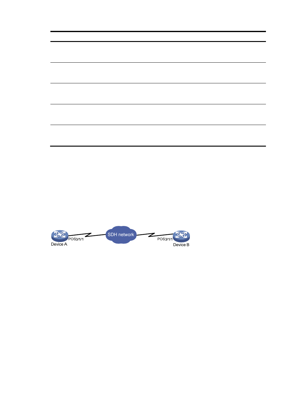
Device A and Device B are connected through the POS interfaces. Device A is equipped with clock
monitoring module on its SRPU.
•
The synchronized clock of Device A is provided by the clock monitoring module on its SRPU.
•
Device B adopts the line clock from Device A to synchronize with the SDH line of Device A.
Figure 33 Network diagram
Configuration procedure
1.
Configure Device A (master clock):
# Set the interface POS 3/1/1 to work in master clock mode, using local clock signals.
<DeviceA> system-view
[DeviceA] interface pos 3/1/1
[DeviceA-Pos3/1/1] clock master
2.
Configure Device B (slave clock):
# Set the LPU port on Device B to POS 3/1/1.
<DeviceB> system-view
[DeviceB] clock lpuport pos 3/1/1
# Set the interface POS 3/1/1 to work in slave clock mode.
[DeviceB] interface pos 3/1/1
[DeviceB-Pos3/1/1] clock slave
[DeviceB-Pos3/1/1] quit