Configuration procedure – H3C Technologies H3C SR8800 User Manual
Page 90
78
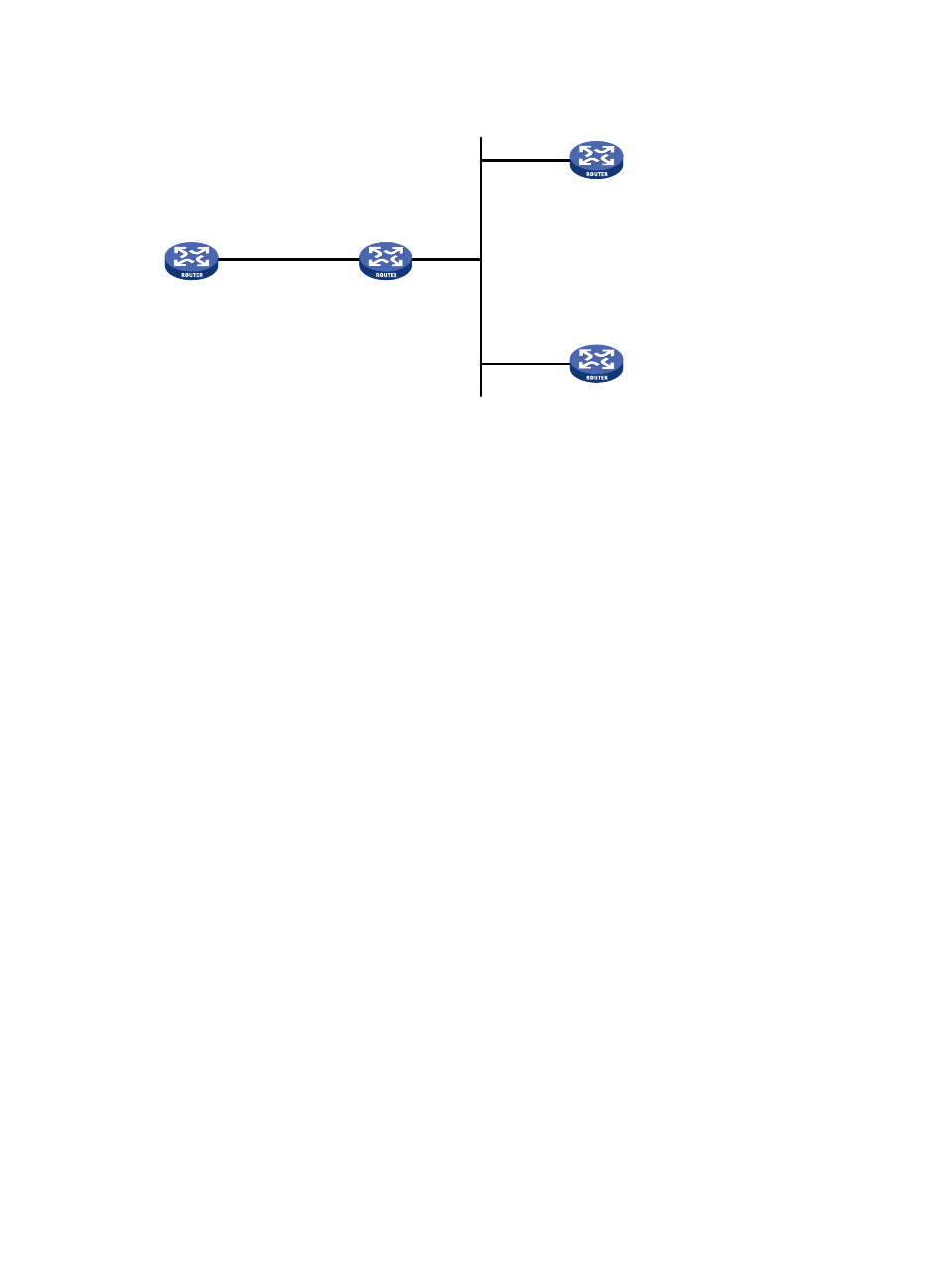
Figure 30 Network diagram
Configuration procedure
1.
Set the IP address for each interface as shown in
. (Details not shown)
2.
Configure Router C:
# Specify the local clock as the reference source, with the stratum level of 3.
<RouterC> system-view
[RouterC] ntp-service refclock-master 3
# Configure NTP authentication
[RouterC] ntp-service authentication enable
[RouterC] ntp-service authentication-keyid 88 authentication-mode md5 123456
[RouterC] ntp-service reliable authentication-keyid 88
# Specify Router C as an NTP broadcast server, and specify an authentication key.
[RouterC] interface GigabitEthernet 3/1/10
[RouterC-GigabitEthernet3/1/10] ntp-service broadcast-server authentication-keyid
88
3.
Configure Router D:
# Configure NTP authentication
<RouterD> system-view
[RouterD] ntp-service authentication enable
[RouterD] ntp-service authentication-keyid 88 authentication-mode md5 123456
[RouterD] ntp-service reliable authentication-keyid 88
# Configure Router D to work in the NTP broadcast client mode
[RouterD] interface GigabitEthernet 3/1/10
[RouterD-GigabitEthernet3/1/10] ntp-service broadcast-client
Now, Router D can receive broadcast messages through GigabitEthernet 3/1/10, and Router C
can send broadcast messages through GigabitEthernet 3/1/10. Upon receiving a broadcast
message from Router C, Router D synchronizes its clock with that of Router C.
# View the NTP status of Router D after clock synchronization.
[RouterD-GigabitEthernet3/1/10] display ntp-service status
Clock status: synchronized
Clock stratum: 4
Reference clock ID: 3.0.1.31
GE3/1/1
1.0.1.10/24
Router A
GE3/1/10
3.0.1.31/24
GE3/1/10
3.0.1.32/24
Router B
Router C
Router D
GE3/1/10
1.0.1.11/24
GE3/1/10
3.0.1.30/24